Sensor beam lifting device used for deflectograph

A sensor and deflection meter technology, applied in the direction of supporting machines, balance weights, mechanical equipment, etc., can solve problems such as out-of-synchronization and easy wear of wire ropes, and achieve the effect of ensuring the adjustment effect and improving the fine-tuning accuracy

Active Publication Date: 2021-12-28
南京侨睿交通技术有限公司
View PDF9 Cites 0 Cited by
  • Summary
  • Abstract
  • Description
  • Claims
  • Application Information

AI Technical Summary

Problems solved by technology

However, the steel wire rope is prone to wear and tear, and is prone to changes in tightness, resulting in asynchronous problems

Method used


Image

  • Sensor beam lifting device used for deflectograph
  • Sensor beam lifting device used for deflectograph
  • Sensor beam lifting device used for deflectograph

Examples


Embodiment Construction

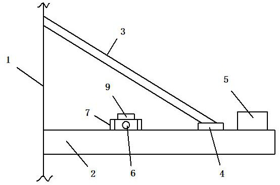
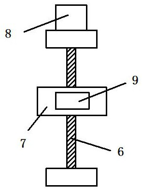
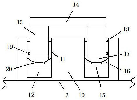
[0015] refer to Figure 1-3 , a specific embodiment of the present invention includes a bearing mechanism 1, one end of the sensor beam 2 is axially connected to the bearing mechanism 1, and a first hydraulic cylinder 3 is axially connected to the bearing mechanism 1, and the piston end of the first hydraulic cylinder 3 is connected to The device 4 is connected to the other end of the sensor beam 2, the first hydraulic cylinder 3 is located above the sensor beam 2, a three-axis gyroscope 5 is installed on the sensor beam 2, and a lead screw 6 is installed on the top surface of the sensor beam 2, and the lead screw 6 is connected to the sensor beam 2. The first hydraulic cylinder 3 is vertical, the screw 6 is equipped with a nut seat 7, the servo motor 8 is connected with the rotating nut (not shown in the figure) in the nut seat 7, and the counterweight 9 is installed on the surface of the nut seat 7, connected The device 4 includes a base 10, on which two sleeves 11 are symme...


PUM


Abstract

The invention discloses a sensor beam lifting device used for a deflectograph. The sensor beam lifting device comprises a bearing mechanism, one end of a sensor beam is in shaft connection to the bearing mechanism, the bearing mechanism is in shaft connection with a first hydraulic cylinder, the piston end of the first hydraulic cylinder is connected to the other end of the sensor beam through a connector, the first hydraulic cylinder is located above the sensor beam, a three-axis gyroscope is installed on the sensor beam, a lead screw is installed on the top face of the sensor beam, a nut seat is installed on the lead screw, a servo motor is connected with a rotating nut in the nut seat, a balancing weight is installed on the surface of the nut seat, the connector comprises a base, two sleeves are symmetrically fixed to the base, second hydraulic cylinders are installed at the bottoms of the two sleeves correspondingly, the piston ends of the second hydraulic cylinders are connected with connecting rods, the tops of the two connecting rods are in shaft connection to the two ends of a top plate correspondingly, and the piston end of the first hydraulic cylinder is fixed to the top plate. By means of the device, the defects in the prior art can be overcome, and the horizontal state of the sensor beam can be automatically monitored and controlled.

Description

technical field [0001] The invention relates to the technical field of deflectometers, in particular to a sensor beam lifting device for a deflectometer. Background technique [0002] The deflection meter is a device that detects the road surface through sensors by applying an impact load to the road surface to cause instantaneous deformation of the road surface. The sensor of the traditional deflection meter is installed on the sensor beam, which is connected to the loading plate through a steel wire, and moves up and down synchronously with the loading plate. However, the steel wire rope is prone to wear and tear, and is prone to changes in tightness, resulting in asynchronous problems. Contents of the invention [0003] The technical problem to be solved by the present invention is to provide a sensor beam lifting device for deflectometers, which can solve the deficiencies of the prior art, automatically monitor and control the horizontal state of the sensor beam, and ...

Claims


Application Information

Patent Timeline
Patent Type & Authority Applications(China)
IPC IPC(8): F16M11/10F16M11/18F16M13/02F16F15/28
CPCF16M11/10F16M11/18F16M13/02F16F15/28
Inventor 王村朱木峰
Owner 南京侨睿交通技术有限公司
Why Eureka
Try Eureka