ore crusher

A pulverizer and ore technology, which is applied in the field of particle ore or stone pulverization, can solve the problems of difficult lifting of the top column of the hammer system, unreasonable design and fixation of the hammer, and large loss of the transmission mechanism, so as to reduce the movement resistance. Small, reasonable force, the effect of reducing power

Active Publication Date: 2016-12-28
周建祥
View PDF5 Cites 0 Cited by
  • Summary
  • Abstract
  • Description
  • Claims
  • Application Information

AI Technical Summary

Problems solved by technology

[0005] In order to solve the existing problems in the prior art, the discharge speed of the multi-point hammer mill in actual use is slow, the top column of the hammer material system is difficult to lift, the loss of the transmission mechanism is large, the design and fixing of the material hammer are unreasonable, and the use cost is high. It is difficult to install and modify, and the idler roller under the push plate cannot withstand the large gravity on the top column and is easy to be damaged. The invention provides an ore crusher, which consists of a frame, a hammer mechanism, a feeding mechanism, and a jacking mechanism. Composed of a hopper and a frame, the frame is composed of a bracket, a bottom plate and a chassis, the bottom plate is installed above the bracket, the box is square, and is installed above the bottom plate, the hammer mechanism is installed in the chassis, the feeding mechanism is installed in the middle of the chassis, and the jacking mechanism is installed on the bottom plate Below, the hopper is installed on the side of the chassis. The outlet of the hopper is located above the feeding mechanism. The hammer mechanism consists of a central shaft, a hammer, an upper fixing plate, a lifting pan, a lifting pan fixing nut and a lower fixing plate. The central axis is located in the chassis. center, the central shaft is set in the steel sleeve, and a nylon sleeve is installed between the steel sleeve and the central shaft. The lower end of the steel sleeve is fixed above the middle of the bottom plate, and the lower end of the central shaft is equipped with rollers. The upper fixed plate is square and installed in the chassis. On the top, there is a middle hole in the middle of the upper fixing plate, and a steel sleeve and a nylon sleeve are fixedly installed above the middle hole. The upper end of the middle shaft passes through the middle hole and is fitted in the nylon sleeve. Two groups, distributed symmetrically on both sides of the central axis. There are many material hammers, which are divided into two groups. The material hammers in each group are dislocated. A protruding ring is processed, the spring is set on the hammer rod above the protruding ring, the lifting plate is square, and a positioning hole is opened on it, the hammer rod below the convex ring is set on the positioning hole of the lifting plate, and the installation hole in the middle of the lifting plate is fixed. Set it on the center shaft and fix it with the fixing nut of the lifting plate. The middle part of the material hammer is set in the positioning hole of the lower fixing plate. The middle axis passes through the middle hole of the lower fixing plate. The shock-absorbing spring is set on the rod, and the hammer head is installed at the lower end of the hammer; the two sides of the upper fixing plate and the lower fixing plate are fixed on the side of the chassis

Method used


Image

  • ore crusher
  • ore crusher
  • ore crusher

Examples


Embodiment

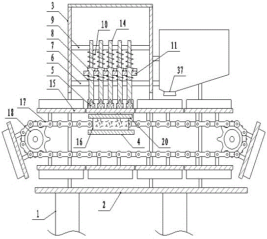
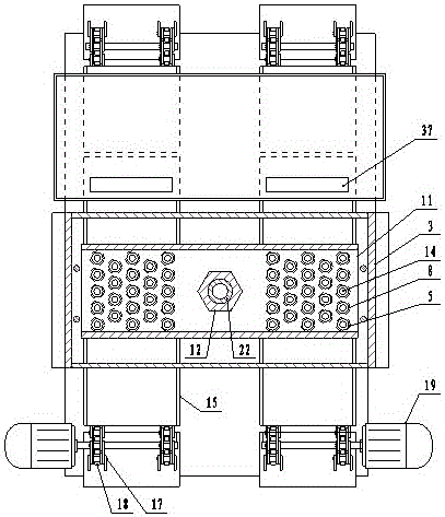
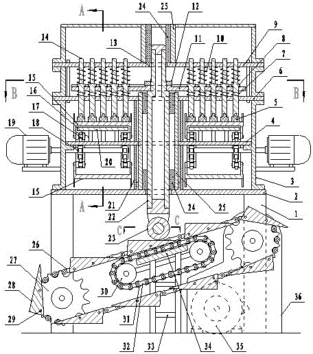
[0013] Example: such as figure 1 , figure 2 , image 3 and Figure 4 As shown, an ore pulverizer is composed of a frame, a hammer mechanism, a feeding mechanism, a jacking mechanism and a hopper. The frame is composed of a bracket 1, a bottom plate 2 and a chassis 3. It is square, installed above the bottom plate 2, the hammer mechanism is installed in the chassis 3, the feeding mechanism is installed in the middle of the chassis 3, the jacking mechanism is installed under the bottom plate 2, the hopper is installed on the side of the chassis, and the outlet 37 of the hopper is located in the feeding mechanism Above, the hammer material mechanism is composed of the central shaft 22, the material hammer 14, the upper fixed plate 9, the lifting tray 11, the lifting pan fixing nut 12 and the lower fixed plate 6. The central axis 22 is located at the center of the cabinet 3, and the central axis 22 is sleeved on the In the steel sleeve 25, a nylon sleeve 24 is installed betwee...


PUM


Abstract

An ore pulverizer is composed of a frame, a hammering mechanism, feeding mechanisms, an up-lifting mechanism, and a hopper. The hammering mechanism is composed of a middle shaft, a hammer, an upper fixing plate, a lifting disc, a lifting disc fixing nut, and a lower fixing plate. Two feeding mechanisms are symmetrically arranged on the two sides of the middle shaft. Each feeding mechanism is composed of a feeding motor, a chain wheel, a feeding plate chain, a feeding plate, a cushion plate, a vertically-supporting plate, and a horizontally-supporting plate. The up-lifting mechanism is composed of a transmission device and a lifting device, the transmission device is composed of a main motor and a gearbox, and the lifting device is arranged on the middle part of the lower support of the bottom plate and is composed of a big chain wheel, a support plate chain, a support plate, a supporting plate, a support rack, a fixed chain wheel, a roller, and a roller chain. The ore pulverizer has the advantages of high efficiency, prominent electric energy saving effect, high ore pulverizing efficiency, large ore output, and convenience for installation and maintenance.

Description

technical field [0001] The invention belongs to the technical field of pulverizers, and is particularly suitable for pulverizing granular ores or stones in mining, metallurgy or cement industries. Background technique [0002] In the metallurgical industry, a large amount of ore needs to be ground and then smelted; in the building material industry, cement production needs to grind the stone and add it to the raw material. In the prior art, ores and stones are generally ground by a ball mill. The ball mill has a huge drum, and steel balls of different diameters are installed in the drum. When the ball mill is working, the granular materials are loaded into the drum, and the drum is driven to rotate. The steel balls and materials are transported from the low end of the drum to the high end during the rotation process, and fall from the high end to the bottom of the drum. When falling to the bottom, the steel balls and materials collide with each other, and the materials are g...

Claims


Application Information

Patent Timeline
Patent Type & Authority Patents(China)
IPC IPC(8): B02C13/06B02C13/286B02C13/28B02C13/30
CPCB02C13/10B02C13/28B02C13/282B02C13/286B02C13/30B02C2013/28618
Inventor 周建祥
Owner 周建祥
Why Eureka
Try Eureka