
Full-automatic leak hunting machine for gloves
A leak detector, fully automatic technology, used in latex glove production equipment, nitrile, and PVC fields, can solve the problems of inability to be used as medical-grade gloves, low inspection accuracy, and lagging inspection results, so as to avoid inspection data errors or quality accidents. , The effect of avoiding human errors and saving testing costs
- Summary
- Abstract
- Description
- Claims
- Application Information
AI Technical Summary
Problems solved by technology
Method used
Image

Examples
Embodiment 1
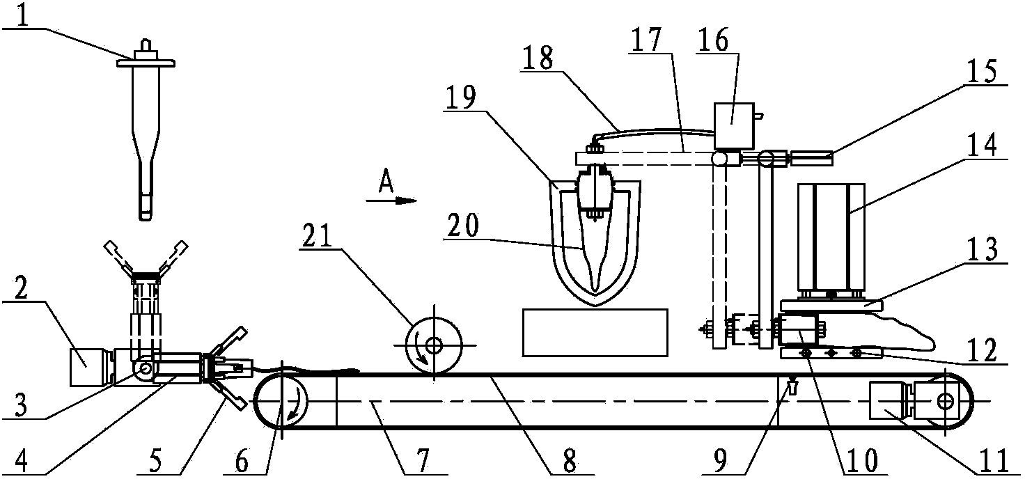
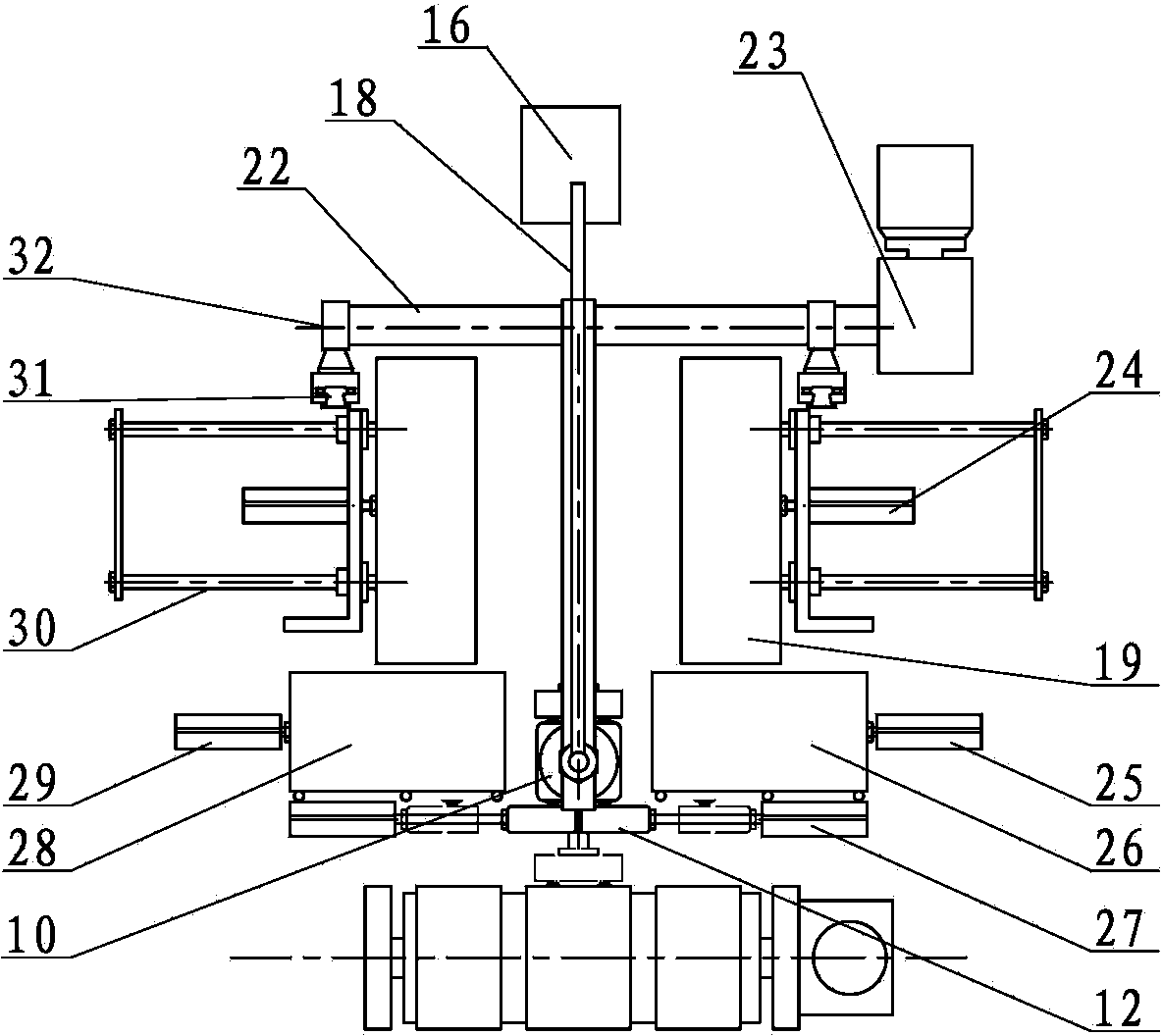
[0039] Such as figure 1 with 2 As shown, in the present invention, the automatic leak detection machine for gloves is composed of the following parts according to the order of operations:
[0040] 1. Glove removal mechanism
[0041] The glove extraction mechanism includes an extraction reduction motor 2, an extraction spindle 3, a lifting cylinder 4 and an extraction air claw 5, the extraction air claw 5 is installed on the lifting cylinder 4, the lifting cylinder 4 is connected to the extraction spindle 3, and the extraction spindle 3. Connect the extraction geared motor 2 and can be driven by the extraction geared motor 2 to rotate.
[0042] The glove picking mechanism is set under the glove production line. When the pre-released gloves move to the picking position, the picking air claw 5 opens and extends with the lifting cylinder 4. After touching the glove, the picking air claw 5 closes the clip. Take, and then retract with the lifting cylinder 4, so as to realize pick...
Embodiment 2
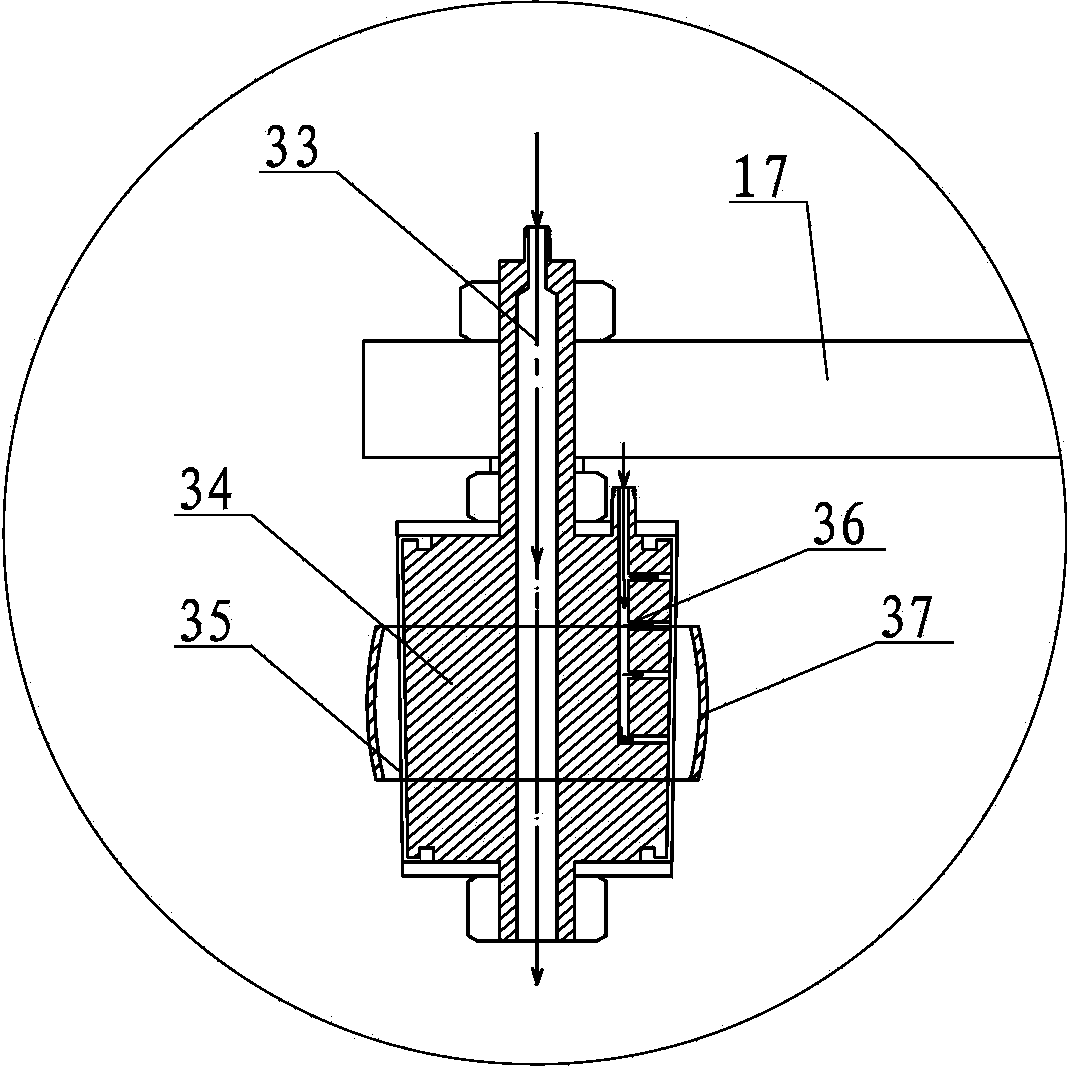
[0073] The difference between this embodiment and the first embodiment lies in the specific structure of the glove inflation joint 10 . Such as Image 6 As shown, the joint main body 34 in the glove inflation joint 10 adopts a cone or truncated cone with one end larger and the other end smaller, and a detection inflation air path 33 is opened in it, and the small end of the joint main body 34 is inserted into the glove first. And a gasket 38 is provided near the big end of the joint body 34. The gasket 38 can move relative to the joint body 34 along the axial direction of the joint body 34 and press against the end surface of the big end of the joint body 34. In this way, the big end of the joint main body 34 is used to tighten the wrist of the glove, and the gasket 38 can also be used to fix the glove for inflation testing.
[0074]Moreover, in this embodiment, the swing reduction motor 23 of the leak detection moving mechanism and the swing arm moving cylinder 15 can be pro...
Embodiment 3
[0077] The difference between this embodiment and Embodiment 1 is that the glove opening mechanism uses the lower suction cup set 12 to first absorb the lower layer of the glove, and then the upper suction cup set 13 moves downward to absorb the upper layer of the glove and then retracts upward to make the glove The upper and lower layers are separated and opened. Its specific structure is: in the vertical direction of the conveyor 6, an open conveyor 39 is provided and a glove transfer mechanism is provided on the side; The transfer cylinder 40 can drive the transfer air sucker group 41 to transfer the gloves on the conveyor 6 to the open conveyor 39 . The in-place photoelectric detection device 9 is arranged on the opening conveyor 39, and the in-position photoelectric detection device 9 can control the start and stop of the glove opening conveyor 39. The lower suction cup group 12 is located on the bottom surface of the working side of the glove conveyor belt where the in-p...
PUM
 Abstract
Description
Claims
Application Information