


Quick Research
Generate reliable direction feasibility study reports for your R&D in just a few steps.

Technical Q&A
Discover and master advanced knowledge NOW. Basics, ideas, possibilities, all at once.

Find Solutions
As an expert in R&D theories, this can generate solutions to your technical problems instantly.

Evaluate Feasibility
Analyze your overall solution with one click, know your potential R&D risks in advance.

Monitor Landscape
Get weekly tech updates, stay abreast of the latest tech innovations and key insights.
ceiling fan
A ceiling fan and fan blade technology, which is applied in the field of ceiling fans with retractable fan blades, and can solve the problems of unsightly and loose fan blades, length limitations of fan blades, etc.
- Summary
- Abstract
- Description
- Claims
- Application Information
AI Technical Summary
Problems solved by technology
Method used
Image


Examples
Embodiment Construction
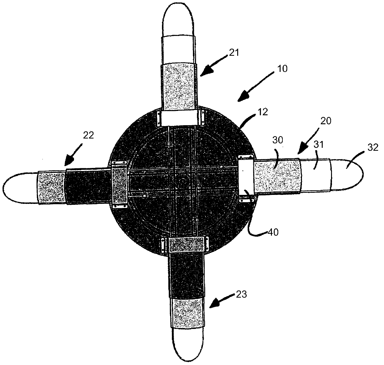
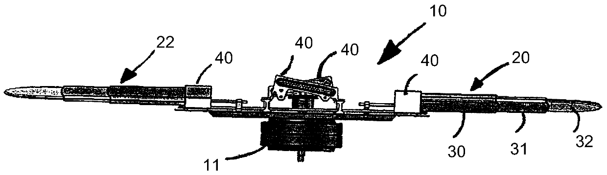
[0017] The ceiling fan 10 shown in the drawings includes an electric motor 11 hung on the ceiling. An electric motor 11 is connected to the circular plate 12, whereby the motor 11 rotates the plate 12 about a vertical axis. The plate 12 is adapted to support four equally spaced fan blade assemblies 20 , 21 , 22 , 23 . Each blade assembly 20 to 23 includes three blade segments 30, 31, 32 that are capable of interacting with each other from a retracted position (FIG. 2) to an outwardly operating position (FIG. 1). Sliding, in the retracted position the blade segments are located within the confines of the plate 12, in the outward operating position the blade segments 30-32 protrude radially outward from the plate 12, thereby facilitating air flow when the plate 12 is rotated by the electric motor 11 . It will be appreciated that the electric motor 11 may be located on the plate 12 or below the plate 12 .
[0018] Each blade assembly 20 - 23 is positioned on the periphery of t...
PUM
 Abstract
Description
Claims
Application Information
 - R&D Engineer
- R&D Manager
- IP Professional
- Industry Leading Data Capabilities
- Powerful AI technology
- Patent DNA Extraction
Browse by: Latest US Patents, China's latest patents, Technical Efficacy Thesaurus, Application Domain, Technology Topic, Popular Technical Reports.
© 2024 PatSnap. All rights reserved.Legal|Privacy policy|Modern Slavery Act Transparency Statement|Sitemap|About US| Contact US: help@patsnap.com