Industrial ceiling fan

a ceiling fan and industrial technology, applied in the field of ceiling fans, can solve the problems of wide open areas of a building, inability to effectively ventilate large areas, etc., and achieve the effect of uniform distribution of airflow

Active Publication Date: 2010-06-01
RITE HITE HLDG CORP +1
View PDF85 Cites 43 Cited by
  • Summary
  • Abstract
  • Description
  • Claims
  • Application Information

AI Technical Summary

Benefits of technology

[0010]In some examples, a resilient bushing helps couple the fan blades to the hub, wherein the bushing helps minimizes stress at the root of the fan blades.
[0011]In some examples, the resilient bushing allows the blades to deflect upward as the speed of the fan increases.
[0015]In some examples, the fan blades are tapered and twisted along their length, and the blades angle of attack is greater near the root of the fan blade than near its tip to more evenly distribute the airflow across the full diameter of the fan.

Problems solved by technology

It can be difficult to effectively ventilate large, wide-open areas of a building such as those areas typically found in warehouses and factories.
Ductwork can be expensive and impractical in some applications, so as a low-cost alternative, a number of ceiling fans might be installed simply to keep the indoor air circulating.
In buildings with high ceilings, however, small fans might not have the capacity to discharge air at a volume that can effectively reach the area near the floor where the occupants could appreciate the airflow, thus small fans might be almost worthless in some cases.
Larger fans might be able to discharge air at a volume and velocity that can reach the floor, however, large fans require more radial clearance, thus they can be more difficult to install between obstacles.
Increasing the speed of the fan can worsen the focused draft problem.
Decreasing the fan speed can eliminate the draft, but operating below the fan's rated speed can be an inefficient use of the fan.
In addition, large fans are inherently heavier and may require creative means for ensuring that the fan and its various parts remain intact.

Method used


Image

  • Industrial ceiling fan
  • Industrial ceiling fan
  • Industrial ceiling fan

Examples


Embodiment Construction

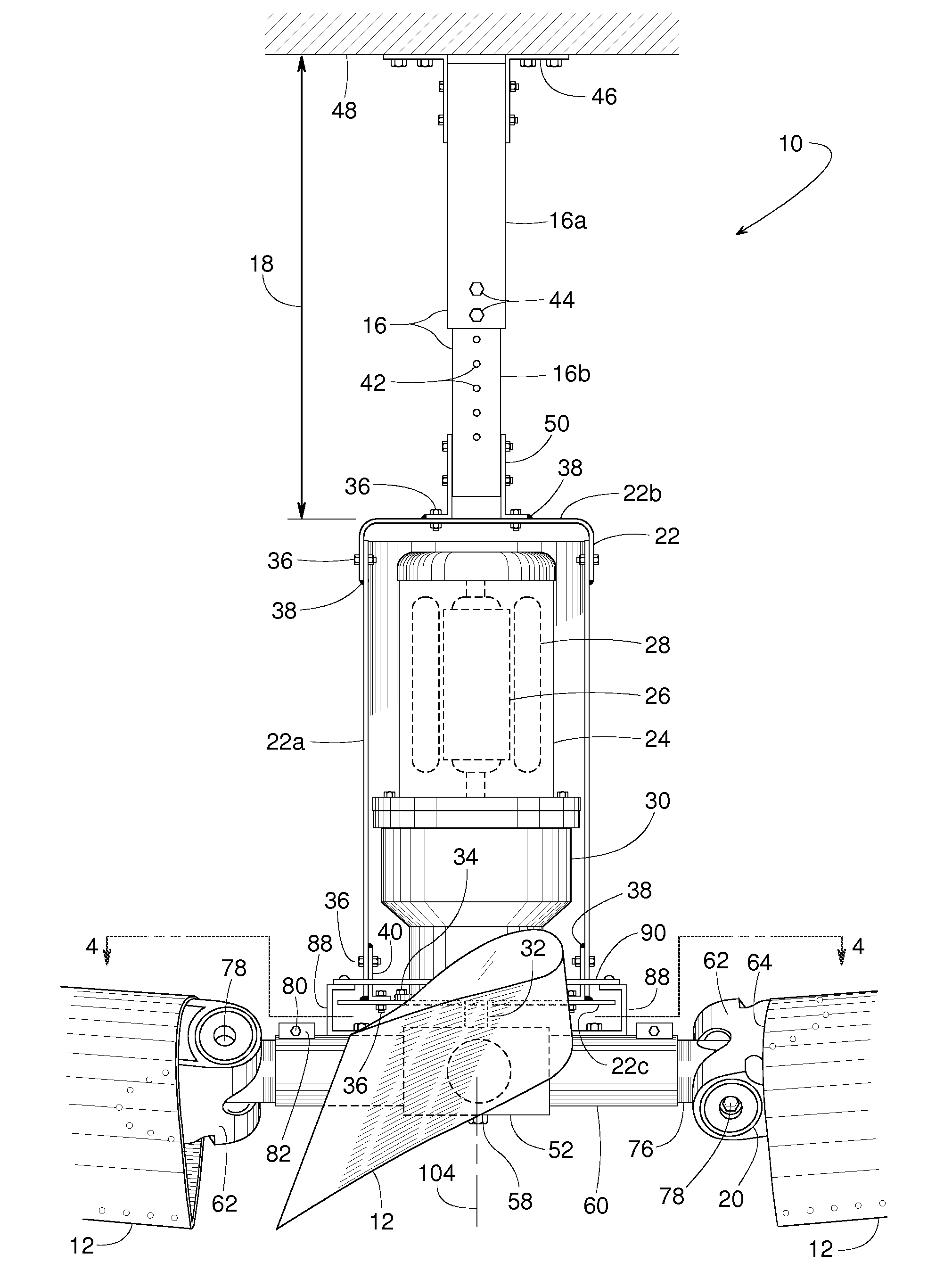
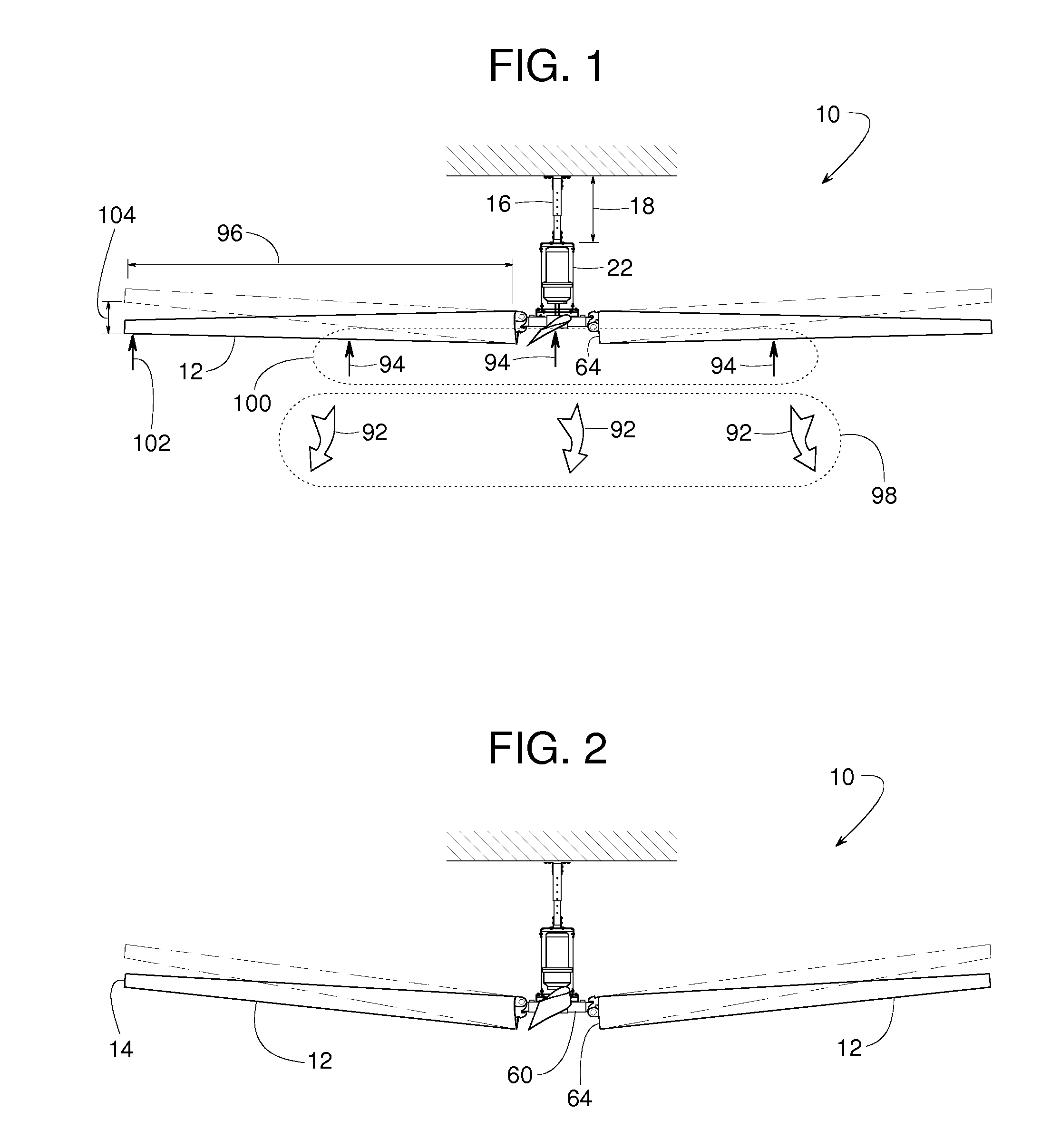
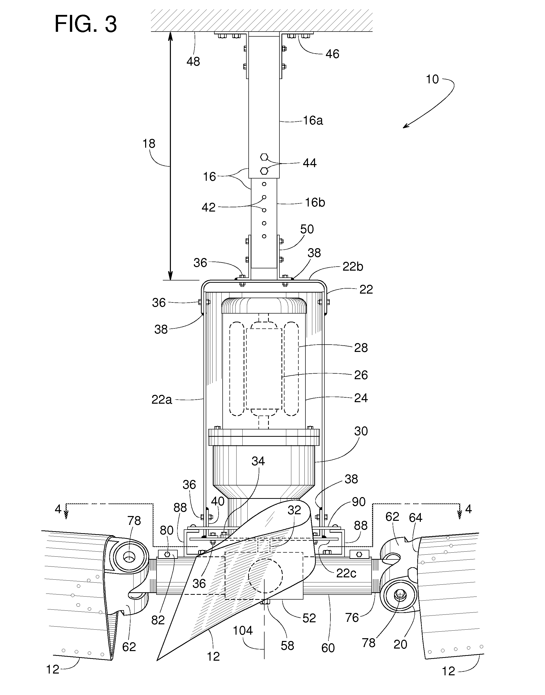
[0021]A ceiling fan 10, illustrated in FIGS. 1-5, includes various features that make fan 10 particularly suited for ventilating large open areas in a building such as in a factory or warehouse. Fan 10, for instance, has fan blades 12 that can be five to twelve feet long (or longer) to ventilate a broad area below the fan 10; fan blades 12 can be tilted lengthwise with a blade tip 14 raised so that fan 10 can cover an even broader area; each fan blade 12 has a shape that varies along its length to promote airflow underneath the full diameter of the fan 10; a hanger 16 has an adjustable length 18 so that fan 10 can be installed at an elevation where fan blades 12 can avoid pipes, hanging light fixtures, overhead beams and various other obstacles often found in industrial buildings; a resilient connector 20 (FIGS. 3 and 4) provides fan blades 12 with strain relief and additional flexibility; and fan 10 includes a bracket assembly 22 with redundant or backup connections for safety.

[002...


PUM


Abstract

A large industrial ceiling fan includes exceptionally long fan blades with blade tips that can be tilted upward to more broadly distribute the air. Such broad distribution might be particularly beneficial in cases where the fan is installed relatively low to avoid obstacles such as hanging lights, sprinkler heads and rafters. A low mounting position is possible, because the fan is suspended from a hanger of adjustable length. The fan includes several joints that are redundantly bolted and welded for safety. A continuous retaining ring provides additional safety. A resilient bushing enhances the flexibility of the fan blades and reduces strain where the fan blades connect to a central mounting hub. To more broadly distribute the airflow underneath the fan, each fan blade has a twisted geometry to provide an angle of attack that decreases from the root to the tip of the blade.

Description

FIELD OF THE DISCLOSURE[0001]The present disclosure generally pertains to ceiling fans and more specifically to industrial ceiling fans.BACKGROUND OF RELATED ART[0002]It can be difficult to effectively ventilate large, wide-open areas of a building such as those areas typically found in warehouses and factories. Ductwork can be expensive and impractical in some applications, so as a low-cost alternative, a number of ceiling fans might be installed simply to keep the indoor air circulating.[0003]An area can be ventilated by a large number of small fans or a fewer number of large fans. Either option has its advantages and disadvantages. Smaller fans can be easier to install between rafters, sprinkler heads, hanging lights and other obstacles found in some buildings. Small fans might also be strategically located to focus the ventilation where it is most needed. In buildings with high ceilings, however, small fans might not have the capacity to discharge air at a volume that can effect...

Claims


Application Information

Patent Timeline
Patent Type & Authority Patents(United States)
IPC IPC(8): F04D25/08F04D29/32F04D29/34F04D29/60F04D29/64
CPCF04D25/088F04D29/329F24F7/007F04D29/601F04D29/646F04D29/34
Inventor GRANT, DONALD P.MALY, PAULMOORE, JOHNSNYDER, RONALD P.WIEGEL, AARON J.
Owner RITE HITE HLDG CORP
Why Eureka
Try Eureka