Quick connect blade iron system

a blade iron and fast technology, applied in the field of ceiling blade irons, can solve the problems of tedious installation of blade irons, etc., and achieve the effect of reducing the number of blade irons and reducing the number of installation steps

Inactive Publication Date: 2005-03-08
HUNTER FAN
View PDF15 Cites 40 Cited by
  • Summary
  • Abstract
  • Description
  • Claims
  • Application Information

AI Technical Summary

Benefits of technology

In a preferred form of the invention a blade iron mounting system which is mounted to an electric motor comprises a blade iron having a blade mounting portion, and a motor mounting portion opposite the blade mounting portion, the motor mounting portion having a vertical portion extending to a horizontal portion, a pair of channels having a enlarged portion extending through the vertical portion and a narrow portion extending into the horizontal portion, and a releasable stop. The system also includes a pair of posts coupled to the motor, each post has a stem portion and a head portion, and spring biasing means for biasably coupling the blade iron to the posts. With this construction, the blade iron is moved in one direction to allow the posts to be slid through the channels while the spring means provides a tight fit between the posts and the mounting portion, and whereby the stops prevent the movement of the mounting portion in an opposite direction.

Problems solved by technology

This however has proven to be a tedious task for those installing the blade irons.

Method used


Image

  • Quick connect blade iron system
  • Quick connect blade iron system
  • Quick connect blade iron system

Examples


Embodiment Construction

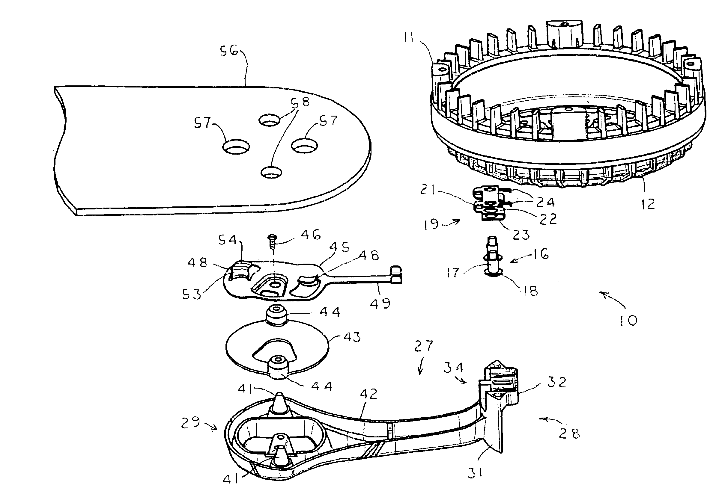
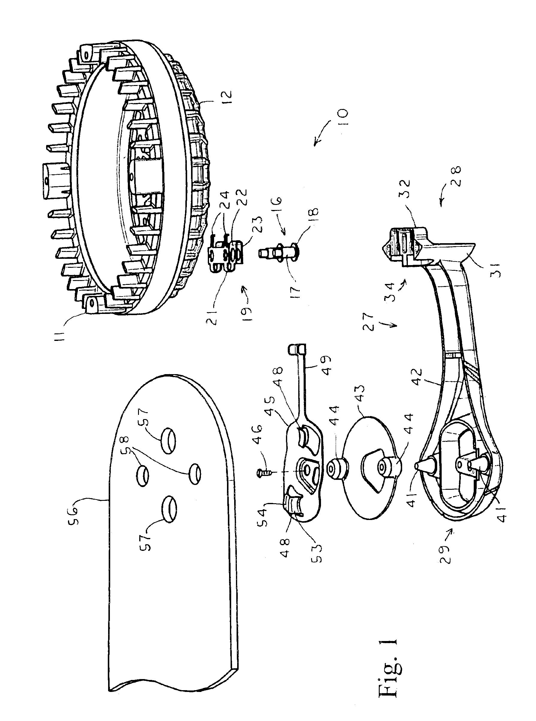
With reference next to the drawings, there is shown a quick connect blade iron system 10 in a preferred form of the invention. The blade iron system 10 is coupled to a conventional ceiling fan electric motor 11 having a lower portion 12. The motor lower portion 12 has an annular array of five, paired, internally threaded mounting holes 13 therein. A post or mounting screw 16, having a stem 17 and a head 18, is mounted within each mounting hole 13. Each post 16 passes through a S-shaped spring 19 having a first leg 21 adjacent the motor lower portion 12, a second leg 22 and a third leg 23. The first leg 21 is configured to include two L-shaped flanges which forms a releasable blade iron stop 24.

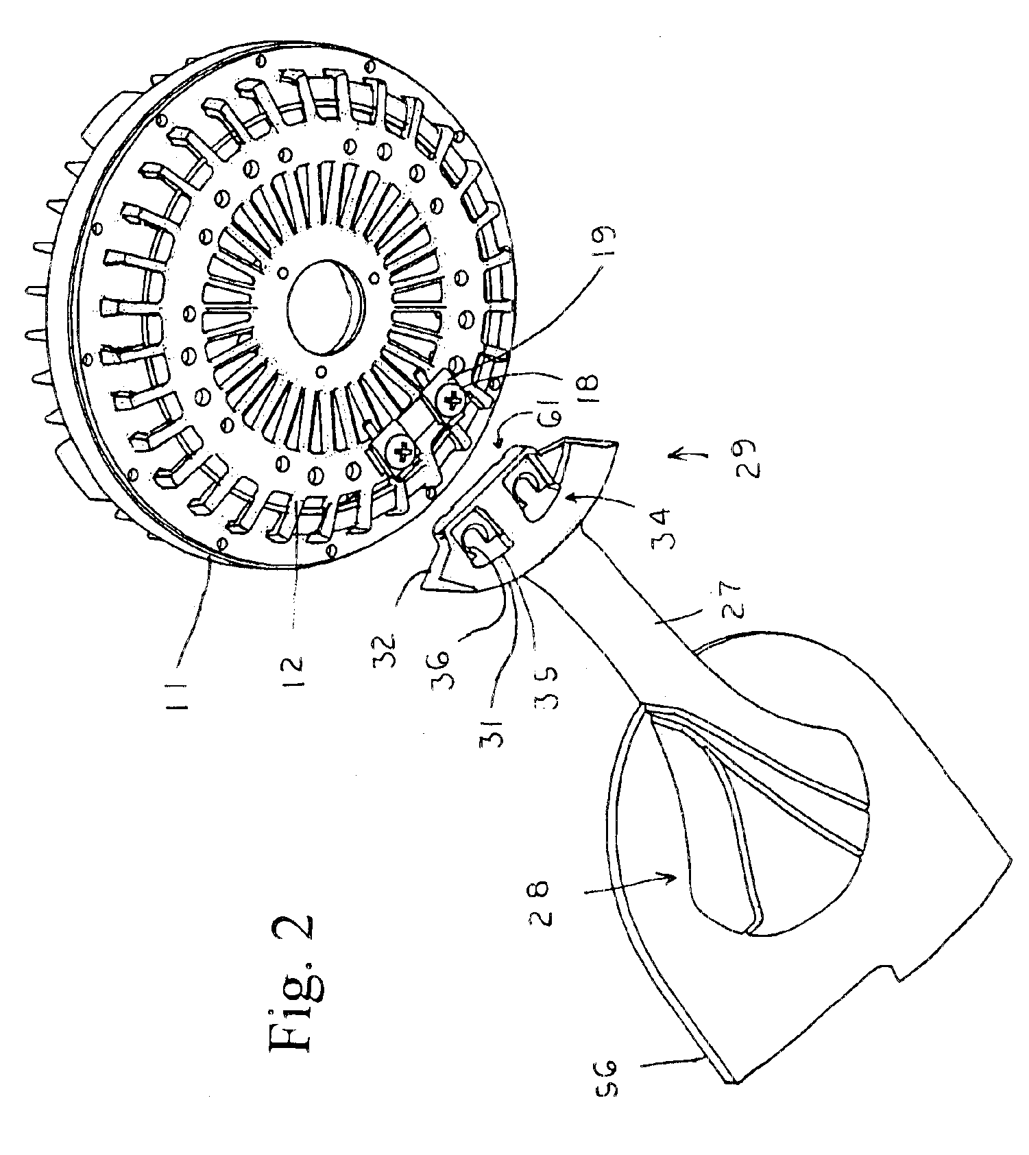
The blade iron system 10 also includes a blade iron 27 having a motor mounting flange or portion 28 and a blade mounting portion 29. The motor mounting portion 28 has a vertical portion or peripheral wall 31 extending to a horizontal portion or abutment wall 32 which abuts the motor lower port...


PUM


Abstract

A ceiling fan quick connect blade iron system (10) is disclosed which is coupled to a conventional ceiling fan electric motor (11) having a lower portion (12). The motor lower portion has an annular array of threaded mounting holes (13) therein. A post (16) having a stem (17) and a head (18) is mounted within each mounting hole (13) and extends through a S-shaped spring (19). The blade iron system also includes a blade iron (27) having a motor mounting flange (28) and a blade mounting portion (29). The motor mounting portion has a vertical portion (31) extending to a horizontal portion (32). The motor mounting portion has a pair of slots (34) which have an enlarged, peripheral portion (35) that extends through the vertical portion (31) to a narrow, inboard portion (36) that extends through the horizontal portion (32). The horizontal portion (32) also includes a recess (37) about each narrow portion (36).

Description

TECHNICAL FIELDThis invention relates to ceiling blade irons, and especially to quick connecting blade irons.BACKGROUND OF THE INVENTIONElectrically powered ceiling fans typically have a motor mounted within a stationary housing that is suspended from a ceiling. In operation, the motor rotates an annular array of individual extensions in the form of blade irons. Each blade iron is associated with a blade mounted thereto.Ceiling fans are usually sold at retail with their blades packed separately from the blade irons and the blades packed separately from the motor for compactness. The housing is normally mounted in suspension from the ceiling through a downrod and then the blades are mounted to the blade irons and the blade irons are mounted to the motor.The blade irons of ceiling fans have typically been mounted to the motor by providing a mounting flange portion of the blade iron with mounting holes through which mounting screws are passed. These mounting screws are threaded into th...

Claims


Application Information

Patent Timeline
Patent Type & Authority Patents(United States)
IPC IPC(8): F04D25/08F04D25/02F04D29/34F04D29/32
CPCF04D29/34F04D25/088
Inventor PEARCE, RICHARD A.
Owner HUNTER FAN
Why Eureka
Try Eureka