Micro-adjustable fuel-burning lamp

A fuel oil and lamp body technology, applied to combustible materials, lighting device parts, lighting devices, etc., can solve the problems of no lifting adjustment function, non-movable fuel lamp, inconvenient use, etc.

Inactive Publication Date: 2015-03-18
张翔
View PDF1 Cites 1 Cited by
  • Summary
  • Abstract
  • Description
  • Claims
  • Application Information

AI Technical Summary

Problems solved by technology

The fuel lamp is not movable and does not have the function of lifting adjustment, which is inconvenient to use

Method used


Image

  • Micro-adjustable fuel-burning lamp

Examples


Embodiment Construction

[0012] In order to make the technical means, creative features, objectives and effects of the present invention easy to understand, the present invention will be further explained below in conjunction with specific embodiments.

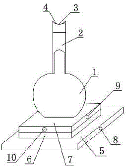
[0013] Such as figure 1 As shown, a fuel lamp that can be finely adjusted includes a fuel lamp body 1 and a bottom plate 5. The bottom plate 5 is provided with a lifting plate 6, and the lifting plate 6 is provided with a moving plate 7, and the fuel lamp body 1 is arranged on the moving plate 7. The side of the bottom plate 5 is provided with a control button 8 for controlling the up and down lifting of the lifting plate 6, a first knob 9 for controlling the movement of the moving plate 7 along the X axis of the lifting plate 6 is provided on the side of the moving plate 7, and on the side of the moving plate 7 A second knob 10 for controlling the movement of the moving plate 7 along the Y axis of the lifting plate 6 is provided. The fuel lamp body 1 is...


PUM


Abstract

The invention discloses a micro-adjustable fuel-burning lamp comprising a fuel lamp body and a baseplate. A lifting plate is arranged on the baseplate, a moving plate is arranged on the lifting plate, the fuel lamp body is disposed on the moving plate, a control button used for controlling the lifting plate to ascend and descend is arranged on the side face of the baseplate, a first knob used for controlling the moving plate to move along the X-axis of the lifting plate is arranged on the side face of the moving plate, and a second knob used for controlling the moving plate to move along the Y-axis of the lifting plate is arranged on the side face of the moving plate. The micro-adjustable fuel-burning lamp is capable of sliding horizontally and vertically and allowing micro-adjustment.

Description

Technical field [0001] The invention relates to a fuel lamp, in particular to a fuel lamp that can be finely adjusted. Background technique [0002] In the prior art, for example, patent ZL200410090958.0 discloses a typical fuel lamp including an oil reservoir, a base, a combustion tube and a wick. The oil reservoir is used to store the supplied oil. The base defines an inner cavity and an opening, the opening communicates with the inner cavity and the size and shape of the opening can accommodate the oil reservoir, and the oil reservoir can be placed in the inner cavity. The combustion tube is mounted on the oil reservoir in a movable manner between a retracted position and an extended position. The combustion tube has a first end, an opposite second end and at least one opening formed between the first end and the second end. In the retracted position, the first and second ends are located in the oil reservoir; in the extended position, the first end is located in the...

Claims


Application Information

Patent Timeline
Patent Type & Authority Applications(China)
IPC IPC(8): F21K5/00F21V21/14
Inventor 张翔
Owner 张翔
Why Eureka
Try Eureka