Valve assembly for controlling the gas pressure, fuel system comprising a valve assembly for controlling the gas pressure

A fuel system and gas pressure technology, applied in the direction of charging system, valve device, valve details, etc., can solve the problems of limited mechanical loadability, bending, etc., and achieve the effect of reducing load and improving functional reliability

Active Publication Date: 2020-08-21
ROBERT BOSCH GMBH
View PDF24 Cites 0 Cited by
  • Summary
  • Abstract
  • Description
  • Claims
  • Application Information

AI Technical Summary

Problems solved by technology

[0004] However, such sealing elements generally have the disadvantage that their mechanical loadability is limited
Furthermore, in the case of bellows seals or bellows seals, there is a risk of buckling if the pressure difference across the seal exceeds a defined limit value

Method used


Image

  • Valve assembly for controlling the gas pressure, fuel system comprising a valve assembly for controlling the gas pressure

Examples


Embodiment Construction

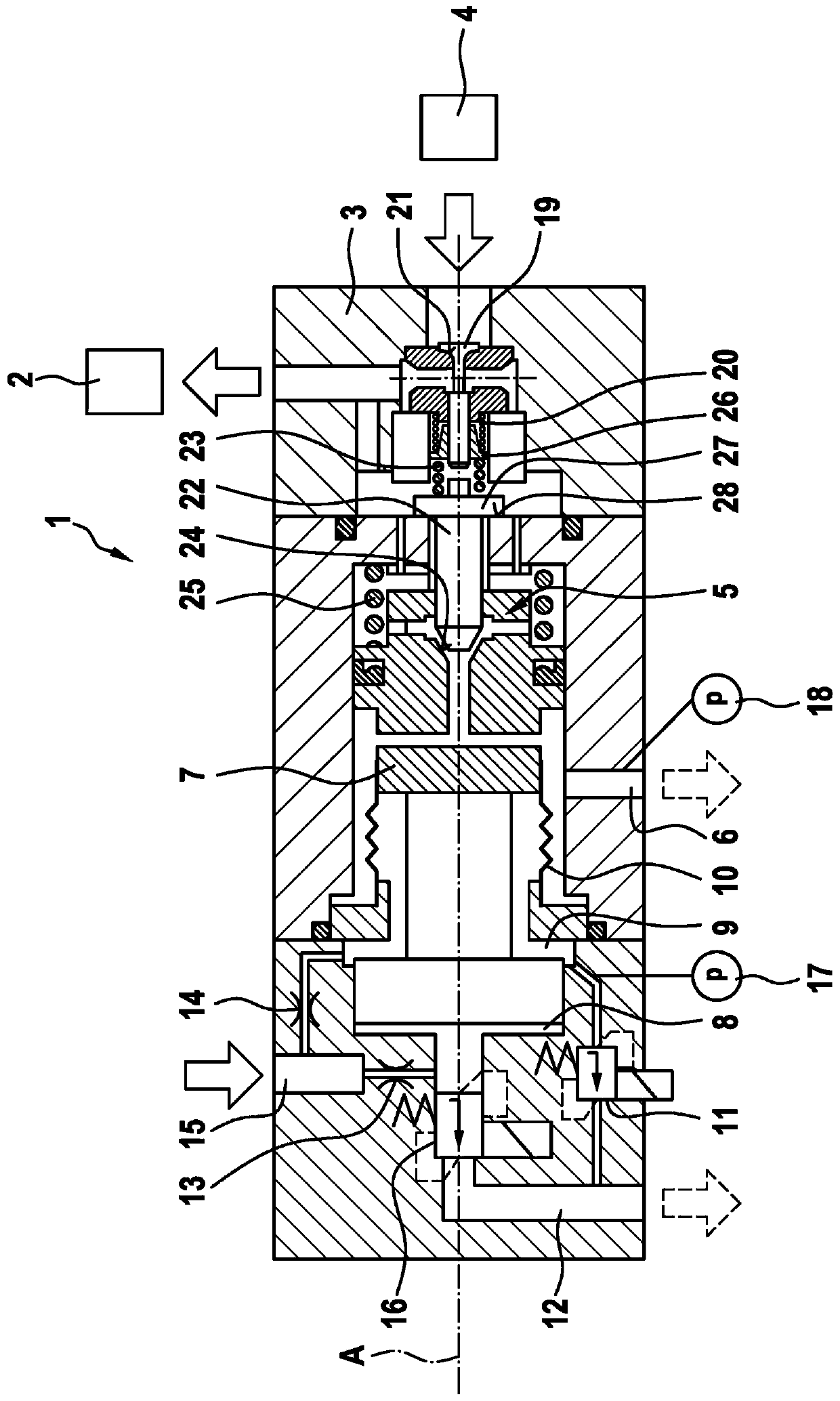
[0022] The valve assembly 1 according to the invention shown in the drawing is used for gas pressure regulation in a gas rail 2 of a fuel system for supplying a gaseous fuel to an internal combustion engine, wherein the gas may in particular be natural gas. For this purpose, the valve arrangement 1 shown has a first valve 3 for connecting the gas rail 2 to the high-pressure accumulator 4 and a second valve 5 for connecting the gas rail 2 to the gas return 6 . The first valve 3 has a valve lifter 19 which can be moved back and forth, which is prestressed against a valve seat 21 by means of a spring 20 . The second valve 5 has a valve piston 22 which is prestressed against a valve seat 24 by means of a spring 23 . For this purpose, the spring 34 is supported on the one side on the valve piston 22 and on the other side on the spring plate 26 connected to the valve tappet 19 . This is possible because the valve piston 22 and the valve tappet 19 are arranged coaxially, ie lie on a...


PUM


Abstract

The invention relates to a valve assembly (1) for controlling the gas pressure in a gas rail (2) of a fuel system for supplying a gaseous fuel, in particular natural gas, to an internal combustion engine, said valve assembly (1) comprising: - a first valve (3) for connecting the gas rail (2) to a high-pressure gas tank (4); - a second valve (5) for connecting the gas rail (2) to a gas recirculation line (6); and - a control piston (7) which runs coaxially to the first and second valves (3, 5) and, in the axial direction, delimits a control chamber (8) which can be exposed to a hydraulic pressure medium. According to the invention, in the radial direction, the control piston (7) delimits a pressure medium leakage chamber (9) which is sealed from the gas recirculation line (6) by a sealing element (10) and can be connected to a pressure medium recirculation line (12) via a pressure medium cut-off valve (11). The invention further relates to a fuel system comprising a valve assembly (1) according to the invention for controlling the gas pressure in a gas rail (2).

Description

technical field [0001] The invention relates to a valve arrangement for gas pressure regulation in a gas rail of a fuel system for supplying an internal combustion engine with a gaseous fuel, in particular natural gas, having the features of the preamble of claim 1 . Furthermore, the invention relates to a fuel system for supplying a gaseous fuel, in particular natural gas, to an internal combustion engine comprising such a valve assembly. Background technique [0002] Laid-open document DE 10 2016 207 743 A1 discloses a fuel system for supplying an internal combustion engine with gaseous fuel, which has a device for metering gaseous fuel to injectors. The device comprises a pressure regulating unit with a shut-off valve, a pressure regulating valve and an overflow valve forming a structural unit. When the shut-off valve is open, the gaseous fuel is metered, wherein the gaseous fuel first reaches the high-pressure accumulator or the gas rail to which at least one injector i...

Claims


Application Information

Patent Timeline
Patent Type & Authority Applications(China)
IPC IPC(8): F02M21/02F02D19/06F16K31/122
CPCF02M21/0215F02M21/0236F02M21/0239F02D19/0605F02D19/0642F02D19/0678F02M21/0233F02D19/022F02D19/027Y02T10/30
Inventor A·谢尔D·瓦勒
Owner ROBERT BOSCH GMBH
Why Eureka
Try Eureka