
camera module

A camera module and lens module technology, which is applied in image communication, radiation control devices, instruments, etc., can solve the problems of unfavorable installation of effective image area, difficulty in reducing frame size, difficulty in miniaturization of mobile terminals, etc., to save wiring area, The effect of reducing side length

Active Publication Date: 2019-07-12
LG INNOTEK CO LTD
View PDF9 Cites 0 Cited by
  • Summary
  • Abstract
  • Description
  • Claims
  • Application Information

AI Technical Summary

Problems solved by technology

Therefore, when a front camera module having a high-pixel image sensor is mounted on a mobile terminal to implement a high-definition video call, the bezel on the mobile terminal is thickened in thickness, and it is difficult to miniaturize the mobile terminal and reduce the size of the bezel. size
[0005] In addition, the conventional front camera module has an effective image area of ​​4:3 ratio which is not supported by high-definition image quality, and the effective image area is unfavorably installed without considering the orientation of the display panel, which is caused by the display panel on the conventional mobile terminal. A structure whose vertical length is longer than its horizontal length
Therefore, when the conventional structure is thus applied to a current mobile terminal such as a smartphone, a video call image is displayed as a vertically cut image, and when the screen is output using the entire space of the display panel, the picture quality degrades

Method used


Image

  • camera module
  • camera module
  • camera module

Examples


Embodiment Construction

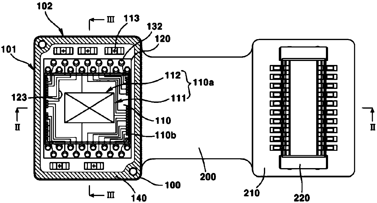
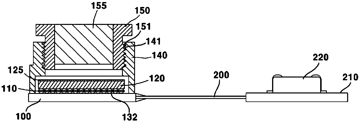
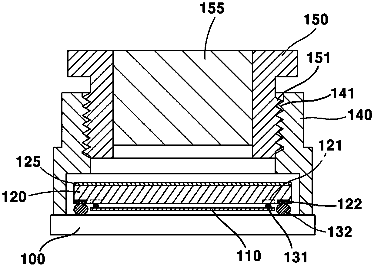
[0041] Various objects, advantages, and features of the present disclosure will become apparent from the following description of the embodiments with reference to the accompanying drawings.

[0042] Therefore, the meaning of the specific terms or words used in this specification and claims should not be limited to the literal or commonly used meaning, but should be interpreted according to the intention of the user or operator and customary usage, or May vary according to user or operator's intention and customary usage. Therefore, the definition of specific terms or words should be based on the contents of the entire specification, and the same reference numerals are used to refer to the same components throughout different drawings.

[0043] Hereinafter, exemplary embodiments of the present disclosure will be described in detail with reference to the accompanying drawings.

[0044] figure 1 is a cross-sectional view showing a PCB of a camera module according to a first ex...


PUM


Abstract

A camera module is provided. A camera module according to an exemplary embodiment of the present disclosure includes: a rectangular image sensor including an effective image area; and a rectangular printed circuit board on which the image sensor is mounted, wherein the effective image area includes a first side and is formed longer than the first side. and wherein the first side is parallel to the long side of the printed circuit board and the second side is parallel to the short side of the printed circuit board.

Description

technical field [0001] Teachings according to exemplary and non-limiting embodiments of the present disclosure relate generally to camera modules, and more particularly to compact camera modules configured for mobile devices. Background technique [0002] This section provides background information related to the present disclosure which is not necessarily prior art. [0003] As the camera module can be miniaturized, the camera module comes to be mountable with various electronic devices including mobile terminals. Along with the improvement of the communication environment and the wide distribution of various mobile terminals capable of video calling, there is a need to develop a front camera module having a high-pixel image sensor capable of performing high-definition video calling. [0004] Generally, a front camera module is arranged at a bezel area of ​​a mobile terminal. However, a front camera module with a high pixel image sensor is larger than a conventional fron...

Claims


Application Information

Patent Timeline
Patent Type & Authority Patents(China)
IPC IPC(8): H04N5/225H04N5/335H01L27/146H04N25/00
CPCH04N23/57G03B21/14
Inventor 郑然白
Owner LG INNOTEK CO LTD
Learn More