An electronic lock wiring structure

A wiring structure and electronic lock technology, applied in the field of electronic locks, can solve the problems of time-consuming and manpower, complicated maintenance, instability, etc., and achieve the effect of convenient installation

Inactive Publication Date: 2017-03-22
惠州市硕玛智控技术有限公司
View PDF6 Cites 0 Cited by
  • Summary
  • Abstract
  • Description
  • Claims
  • Application Information

AI Technical Summary

Problems solved by technology

[0002] The existing electronic locks generally adopt a split structure, including the left lock body and the right lock body, which are installed on both sides of the door body, and the middle needs to be connected by wires. Therefore, it is necessary to open a special threading hole on the door body. Considering the installation needs, The threading hole is generally large, which affects the overall structural strength of the door body. Even if the threading hole is large, the burrs generated around the threading hole are still easy to cut the wire, resulting in circuit damage or unstable operation; The installation process of this method is relatively complicated, requiring multiple people to coordinate the installation, which consumes time and manpower, and the later maintenance is more complicated
It can be seen from the above that there are many problems with the existing electronic lock wiring structure, for this reason, the present invention provides an electronic lock wiring structure to replace the existing wiring structure, and solve the above problems

Method used


Image

  • An electronic lock wiring structure
  • An electronic lock wiring structure
  • An electronic lock wiring structure

Examples


Embodiment Construction

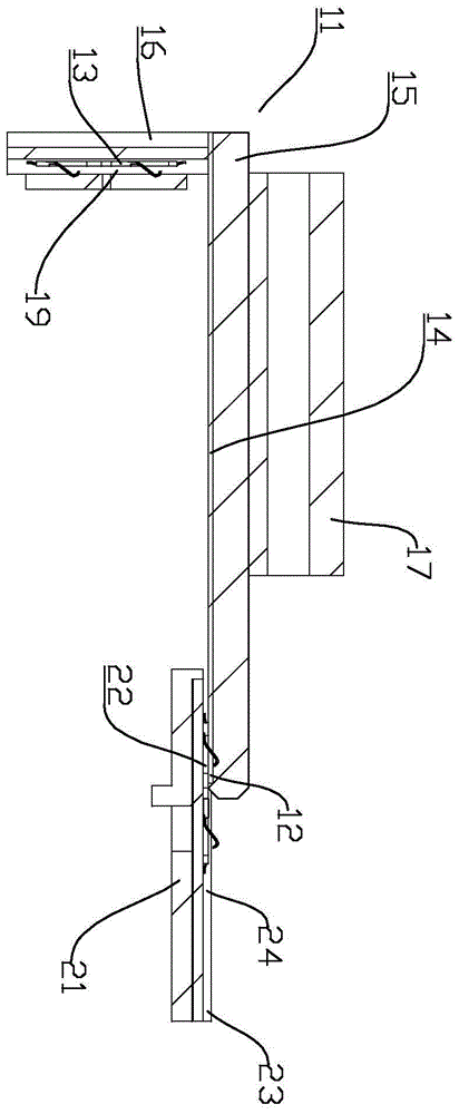
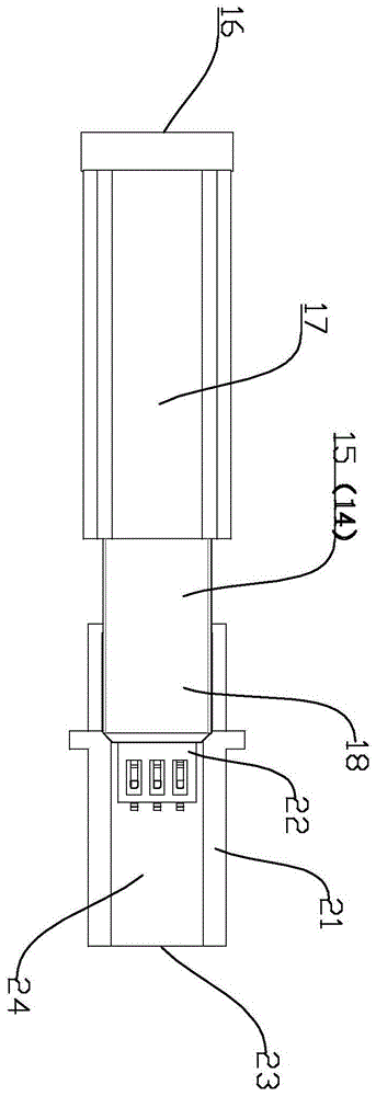
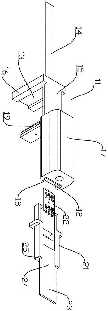
[0019] refer to Figure 1 ~ Figure 3 , the present invention is an electronic lock wiring structure, including a left wiring assembly and a right wiring assembly, one end of the left wiring assembly is electrically connected to the left lock body, one end of the right wiring assembly is electrically connected to the right lock body, and the other end of the left wiring assembly is connected to the right The other end of the wiring assembly can be contacted, the length of the contact part can be adjusted, and the contact part is electrically connected. The present invention adopting the above-mentioned structure contacts and electrically connects the left wiring assembly and the right connecting assembly at one end, and the contact length is adjustable so that the present invention can be applied to thicker doors, while the left wiring assembly and the right connecting assembly belong to the overlapping form. The connection does not need to use card joints and wires, and the in...


PUM


Abstract

The invention discloses a novel wiring structure of an electronic lock. The novel wiring structure comprises a left wiring component and a right wiring component, wherein one end of the left wiring component is electrically connected with a left lock body, and one end of the right wiring component is electrically connected with a right lock body; the other end of the left wiring component can be in contact with the other end of the right wiring component, the length of the contact part can be adjusted, and the left wiring component is electrically connected with the right wiring component at the contact part. According to the structure, the left wiring component and the right wiring component are in contact with each other at certain ends and are electrically connected with each other, and the contact length can be adjusted, so that the novel wiring structure is suitable for a door body with a certain thickness; furthermore, the left wiring component and the right wiring component are connected with each other in a lap joint form, so that a clamping connector and an electric wire are not needed, the novel wiring structure is very convenient to install, and the phenomenon that the electric wire is scratched is avoided.

Description

technical field [0001] The invention relates to the field of electronic locks, in particular to an electronic lock wiring structure. Background technique [0002] The existing electronic locks generally adopt a split structure, including the left lock body and the right lock body, which are installed on both sides of the door body, and the middle needs to be connected by wires. Therefore, it is necessary to open a special threading hole on the door body. Considering the installation needs, The threading hole is generally large, which affects the overall structural strength of the door body. Even if the threading hole is large, the burrs generated around the threading hole are still easy to cut the wire, resulting in circuit damage or unstable operation; The installation process of this method is relatively complicated, requiring multiple people to coordinate the installation, which consumes time and manpower, and the later maintenance is more complicated. It can be seen fro...

Claims


Application Information

Patent Timeline
Patent Type & Authority Patents(China)
IPC IPC(8): E05B47/00
Inventor 邓国文杨林郝生根
Owner 惠州市硕玛智控技术有限公司
Why Eureka
Try Eureka