Automobile brake pedal structure

A technology of automobile brakes and pedals, applied in the field of automobiles, can solve the problems of not being able to adapt to different drivers' driving postures and affecting driving comfort performance, and achieve the effects of improving comfort performance, high connection reliability, and simple structure

Active Publication Date: 2015-04-08
CHERY COMML VEHICLE ANHUI
View PDF6 Cites 7 Cited by
  • Summary
  • Abstract
  • Description
  • Claims
  • Application Information

AI Technical Summary

Problems solved by technology

Everyone's driving posture is different. The existing brake pedal tilt angle is fixed, which cannot adapt to different drivers' driving postures and affects driving comfort.

Method used


Image

  • Automobile brake pedal structure
  • Automobile brake pedal structure
  • Automobile brake pedal structure

Examples


Embodiment Construction

[0018] The specific implementation manner of the present invention will be described in further detail below by describing the embodiments with reference to the accompanying drawings.

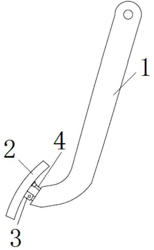
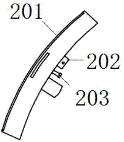
[0019] Such as Figure 1 to Figure 3 As shown, the automobile brake pedal structure includes a pedal arm 1 and a pedal pad 2, the pedal pad 2 is arranged at the lower end of the pedal arm 1, and the upper end of the pedal arm 1 is connected with the brake vacuum booster.

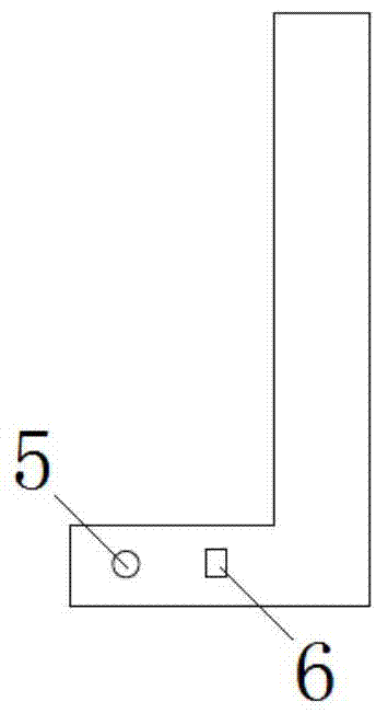
[0020] The back of the pedal pad 2 and the lower end of the pedal arm 1 are hinged by connecting parts; specifically, the connecting parts include a connecting seat 3 and a connecting rod 6, the connecting seat 3 is fixed on the back of the pedal pad 2, and the connecting rod 6 is fixed on the The end of the pedal arm 1, the connecting base 3 and the connecting rod 6 are hinged through a rotating shaft.

[0021] The inclination angle between the pedal pad 2 and the pedal arm 1 can be adjusted, and can be adjusted according t...


PUM


Abstract

The invention discloses an automobile brake pedal structure which comprises a pedal arm and a pedal pad, wherein the back surface of the pedal pad is hinged to the end part of the pedal arm through a connecting part; a rotatable connecting sleeve is arranged on the back surface of the pedal pad; a pedal adjusting bolt in threaded connection with the connecting sleeve is arranged at the end part of the pedal arm. According to the automobile brake pedal structure, an inclination angle between the pedal pad and the pedal arm can be adjusted only by rotating the pedal adjusting bolt, so that the automobile brake pedal structure is convenient to adjust, simple in structure, low in cost and high in connection reliability, and driving comfort is improved.

Description

technical field [0001] The invention relates to the technical field of automobiles, in particular to an automobile brake pedal structure. Background technique [0002] Car braking applies force to the brake pedal through the driver's foot movement, and the brake pedal transmits force to the vacuum booster. After boosting, the brake master cylinder is driven to build up the pressure of the entire brake line, and the pressure will push the brake Braking is achieved by restricting the rotation of the wheels. [0003] With the rapid development of automobile technology, people have higher and higher requirements for driving comfort. Everyone's driving posture is different, and the existing brake pedal inclination angle is fixed, which cannot adapt to different driving postures of drivers and affects driving comfort. Contents of the invention [0004] Aiming at the deficiencies in the prior art, the technical problem to be solved by the present invention is to provide an auto...

Claims


Application Information

Patent Timeline
Patent Type & Authority Applications(China)
IPC IPC(8): B60T7/06
CPCB60T7/06
Inventor 朱亚伟孙茂张锐闫成权
Owner CHERY COMML VEHICLE ANHUI
Why Eureka
Try Eureka