Matrix converter
A matrix converter and power conversion technology, applied in the field of matrix converters, can solve problems such as open-circuit commutation failure of the output phase, error, short-circuit commutation failure between input phases, etc.
- Summary
- Abstract
- Description
- Claims
- Application Information
AI Technical Summary
Problems solved by technology
Method used
Image


Examples
no. 1 approach
[0083] [1.1. Structure of matrix converter]
[0084] figure 1 It is a diagram showing a configuration example of the matrix converter of the first embodiment. Such as figure 1 As shown, the matrix converter 1 of the first embodiment is provided between a three-phase AC power source 2 (hereinafter simply referred to as AC power source 2 ) and a load 3 . Load 3 is, for example, an AC motor. Hereinafter, the R-phase, S-phase, and T-phase of the AC power supply 2 are referred to as input phases, and the U-phase, V-phase, and W-phase of the load 3 are referred to as output phases.
[0085] Matrix converter 1 has: input terminals Tr, Ts, Tt; output terminals Tu, Tv, Tw; power conversion unit 10; LC filter 11; input voltage detection unit 12; output current detection unit 13; Matrix converter 1 converts three-phase AC power supplied from AC power supply 2 via input terminals Tr, Ts, Tt into three-phase AC power of arbitrary voltage and frequency, and outputs it to load 3 through ...
no. 2 approach
[0249] Next, a matrix converter of the second embodiment will be described. The matrix converter of the second embodiment differs from the matrix converter 1 of the first embodiment in that a commutation control unit is selected according to an output voltage vector. In addition, the following description will focus on the differences from the matrix converter 1 of the first embodiment, and components having the same functions as those of the first embodiment will be given the same reference numerals and their descriptions will be omitted.
[0250] Figure 29 It is a diagram showing a configuration example of a matrix converter 1A according to the second embodiment. Such as Figure 29 As shown, matrix converter 1A of the second embodiment includes power conversion unit 10 , LC filter 11 , input voltage detection unit 12 (not shown), output current detection unit 13 , control unit 14A, and output voltage detection unit 15 . The output voltage detection unit 15 detects output...
no. 3 approach
[0268] Next, a matrix converter of a third embodiment will be described. The matrix converter of the third embodiment differs from the matrix converter 1 of the first embodiment in that a commutation control unit is selected according to an input voltage vector. In addition, the following description will focus on the differences from the matrix converter 1 of the first embodiment, and components having the same functions as those of the first embodiment will be given the same reference numerals and their descriptions will be omitted.
[0269] Figure 30 It is a diagram showing a configuration example of the matrix converter 1B of the third embodiment. Such as Figure 30 As shown, the matrix converter 1B of the third embodiment includes a power conversion unit 10 , an LC filter 11 , an input voltage detection unit 12 , an output current detection unit 13 , and a control unit 14B.
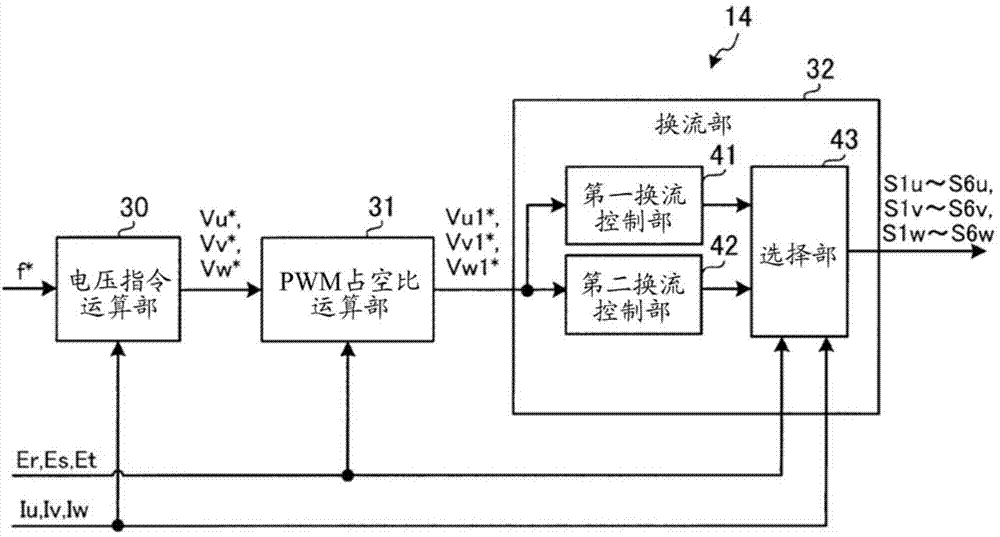
[0270] The control unit 14B includes a voltage command calculation unit 30 (not shown), a PWM...
PUM
 Abstract
Description
Claims
Application Information
 - R&D
- Intellectual Property
- Life Sciences
- Materials
- Tech Scout
- Unparalleled Data Quality
- Higher Quality Content
- 60% Fewer Hallucinations
Browse by: Latest US Patents, China's latest patents, Technical Efficacy Thesaurus, Application Domain, Technology Topic, Popular Technical Reports.
© 2025 PatSnap. All rights reserved.Legal|Privacy policy|Modern Slavery Act Transparency Statement|Sitemap|About US| Contact US: help@patsnap.com