Matrix converter
一种矩阵变换器、电力转换的技术,应用在矩阵变换器领域,能够解决输入相相间短路换流失败、误差、滞后电流检测等问题
- Summary
- Abstract
- Description
- Claims
- Application Information
AI Technical Summary
Problems solved by technology
Method used
Image

Examples
no. 1 approach
[0077] [1.1. Structure of matrix converter]
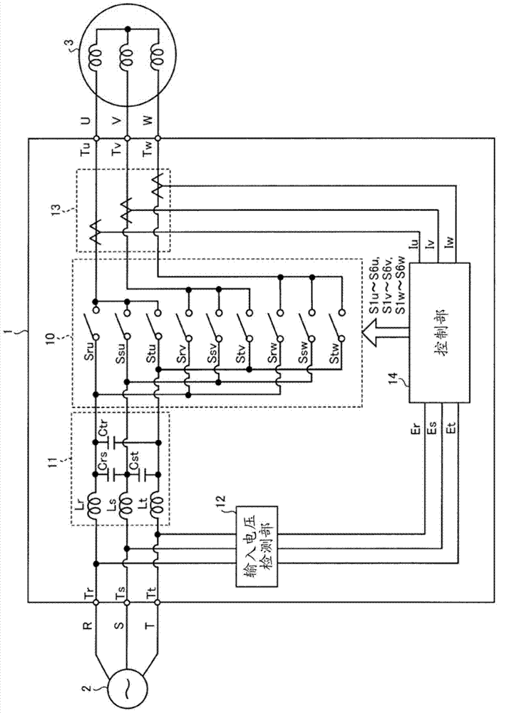
[0078] figure 1 It is a diagram showing a configuration example of the matrix converter of the first embodiment. Such as figure 1 As shown, the matrix converter 1 of the first embodiment is provided between a three-phase AC power source 2 (hereinafter simply referred to as AC power source 2 ) and a load 3 . Load 3 is, for example, an AC motor. Hereinafter, the R-phase, S-phase, and T-phase of the AC power supply 2 are referred to as input phases, and the U-phase, V-phase, and W-phase of the load 3 are referred to as output phases.
[0079] Matrix converter 1 has: input terminals Tr, Ts, Tt; output terminals Tu, Tv, Tw; power conversion unit 10; LC filter 11; input voltage detection unit 12; output current detection unit 13; Matrix converter 1 converts three-phase AC power supplied from AC power supply 2 via input terminals Tr, Ts, Tt into three-phase AC power of arbitrary voltage and frequency, and outputs it to load 3 through ...
no. 2 approach
[0183] Next, a matrix converter of the second embodiment will be described. The matrix converter of the second embodiment differs from the matrix converter 1 of the first embodiment in that a commutation control unit is selected according to an input voltage phase. In addition, the following description will focus on the differences from the matrix converter 1 of the first embodiment, and components having the same functions as those of the first embodiment will be given the same reference numerals and their descriptions will be omitted.
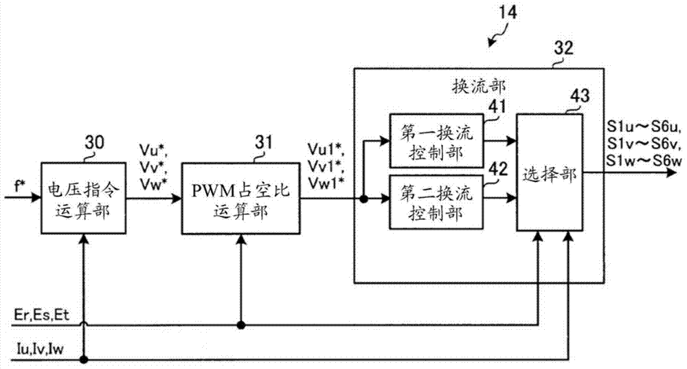
[0184] Figure 21 It is a diagram showing a configuration example of a matrix converter 1A according to the second embodiment. Such as Figure 21 As shown, matrix converter 1A of the second embodiment includes power conversion unit 10 , LC filter 11 , input voltage detection unit 12 , output current detection unit 13 , and control unit 14A.
[0185] The control unit 14A includes a voltage command calculation unit 30 (not shown), a PWM dut...
no. 3 approach
[0211] Next, a matrix converter of a third embodiment will be described. The matrix converter of the third embodiment differs from the matrix converter 1 of the first embodiment in that a commutation control unit is selected according to the output current phase θo and the input voltage phase θi. In addition, the following description will focus on the differences from the matrix converter 1 of the first embodiment, and components having the same functions as those of the first embodiment will be given the same reference numerals and their descriptions will be omitted.
[0212] Figure 24 It is a diagram showing a configuration example of the matrix converter 1B of the third embodiment. Such as Figure 24 As shown, the matrix converter 1B of the third embodiment has a control unit 14B. In addition, although not shown, the matrix converter 1B further includes a power conversion unit 10 , an LC filter 11 , an input voltage detection unit 12 , an output current detection unit ...
PUM
 Abstract
Description
Claims
Application Information
 - R&D
- Intellectual Property
- Life Sciences
- Materials
- Tech Scout
- Unparalleled Data Quality
- Higher Quality Content
- 60% Fewer Hallucinations
Browse by: Latest US Patents, China's latest patents, Technical Efficacy Thesaurus, Application Domain, Technology Topic, Popular Technical Reports.
© 2025 PatSnap. All rights reserved.Legal|Privacy policy|Modern Slavery Act Transparency Statement|Sitemap|About US| Contact US: help@patsnap.com