Cameras for Vehicles

A technology for a camera device and a vehicle, which is applied to vehicle components, optical observation devices, image communication, etc., can solve the problem of not obtaining clear images, and achieve the effect of reducing costs

Active Publication Date: 2017-09-26
HONDA MOTOR CO LTD
View PDF1 Cites 0 Cited by
  • Summary
  • Abstract
  • Description
  • Claims
  • Application Information

AI Technical Summary

Problems solved by technology

[0005] However, in the camera head described in Patent Document 1, the objective lens of the camera head protrudes downward from the lower surface of the rearview mirror housing, so it flows from above along the outer surface of the rearview mirror housing under the action of gravity. Raindrops or snow below, or raindrops or snow flowing from the front to the rear along the outer surface of the rearview mirror housing under the blowing action of the wind blowing from the front of the vehicle, may not be able to obtain clear images. image

Method used


Image

  • Cameras for Vehicles
  • Cameras for Vehicles
  • Cameras for Vehicles

Examples


Embodiment Construction

[0023] Below, refer to Figure 1 ~ Figure 4 Embodiments of the present invention will be described.

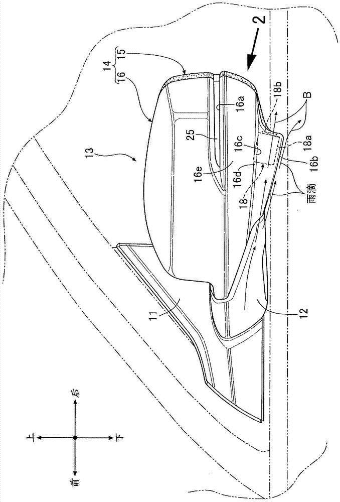
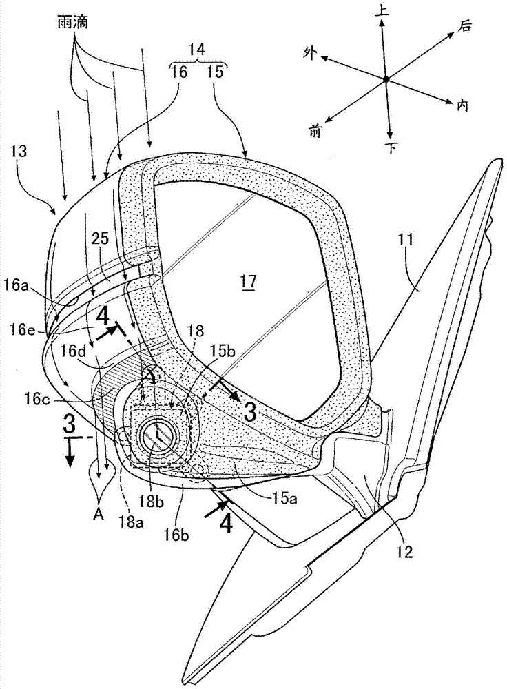
[0024] Such as figure 1 and figure 2 As shown, a triangular substrate 11 is fixed on the front part of the door glass of the front door, and a rearview mirror support part 12 is arranged on the substrate 11, on which a rearview mirror support part 12 is supported for the driver to observe the vehicle body. The rear-view mirror 13 protrudes outward in the vehicle width direction. The mirror 13 is swingable relative to the mirror support portion 12 by an unillustrated retracting mechanism, and can be swung to a position parallel to the extending direction of the door glass so as not to interfere when parking the vehicle or the like.

[0025] A mirror housing 14 constituting the outline of the mirror 13 is formed by connecting a rear housing 15 on the vehicle rear side and a front housing 16 on the vehicle front side with a sealing member. exist figure 1 and figure 2 , th...


PUM


Abstract

The invention provides a vehicle imaging device, which comprises a camera (18) for capturing images of the rear side of a vehicle body housed inside a rearview mirror casing (14) of a rearview mirror (13). Since the objective lens (18b) of the camera (18) is arranged at a position more inside than the outer surface of the rearview mirror housing (14), it can prevent the flow from above along the outer surface of the rearview mirror housing (14) under the action of gravity. The raindrops or snow below, or the raindrops or snow flowing from the front to the rear along the outer surface of the rearview mirror housing (14) under the blowing action of the wind blown from the front of the vehicle, get on the objective lens (18b) of the camera (18) ), so that the camera function of the camera (18) can be maintained.

Description

technical field [0001] The present invention relates to an imaging device for a vehicle in which a camera for capturing an image of the rear side of a vehicle body is housed in a mirror housing of a rearview mirror. Background technique [0002] It is known that the following Patent Document 1 has a structure in which a camera is housed inside a rearview mirror of an automobile, and the road surface conditions near the front wheels can be photographed and confirmed by the camera. [0003] The camera described in Patent Document 1 is used to take pictures of the blind spot area that the driver cannot see. It is equipped with a route monitoring camera or a multi-view camera, wherein the route monitoring camera is used to shoot white lines on the road surface, etc.; the multi-view camera has a fisheye lens with a larger viewing angle. [0004] [Patent Document 1] Japanese Invention Patent Laid-Open Publication No. 2009-93882 [0005] However, in the camera head described in P...

Claims


Application Information

Patent Timeline
Patent Type & Authority Patents(China)
IPC IPC(8): B60R1/06B60R1/00B60R1/12
CPCB60R11/04B60R2011/004B60R2001/1253H04N23/55H04N23/51H04N23/54B60R1/12B60R2011/0043B60R2300/802B60R2300/8066
Inventor 忍田圭渡边崇西口辽彦
Owner HONDA MOTOR CO LTD
Why Eureka
Try Eureka