safety slam lock

A safe and lock cylinder technology, which is applied in the field of locking and impact locks on the floor of train carriages, can solve the problems of few working states, inconvenient use, low reliability, etc., and achieve the effect of more working states and convenient use

Active Publication Date: 2017-01-25
SUZHOU D SNAP TECH
View PDF5 Cites 0 Cited by
  • Summary
  • Abstract
  • Description
  • Claims
  • Application Information

AI Technical Summary

Problems solved by technology

[0004] The invention provides a safety strike lock, which aims to solve the problems of low reliability, inconvenient use and few working states of the existing strike lock

Method used


Image

  • safety slam lock
  • safety slam lock
  • safety slam lock

Examples


Embodiment

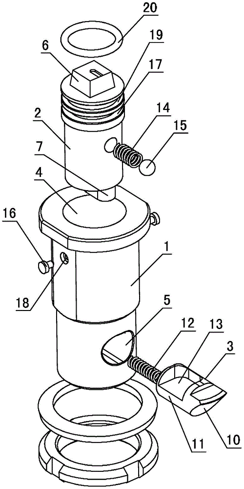
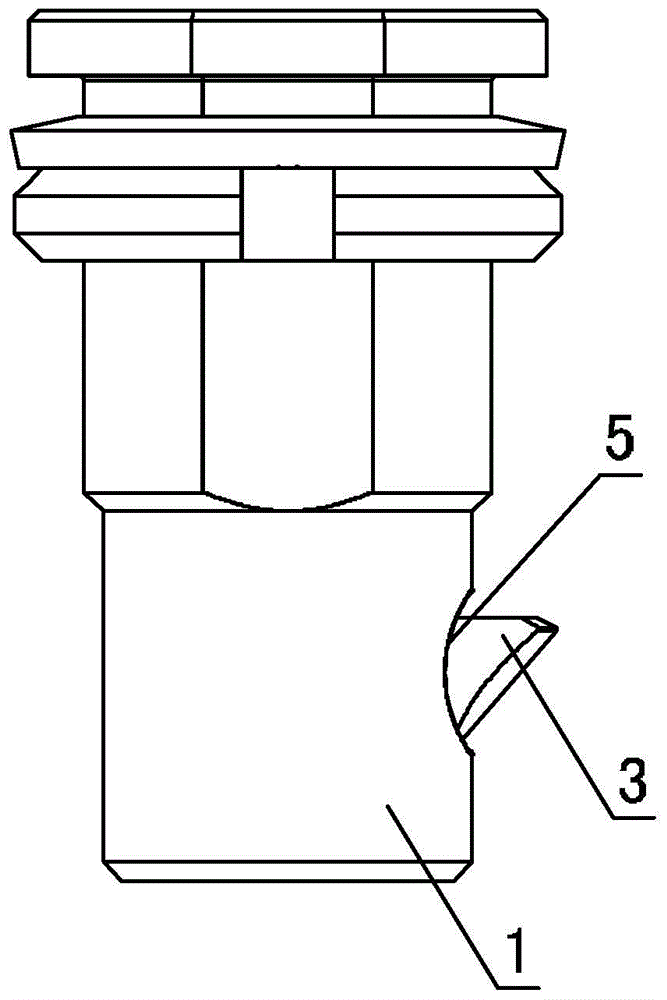
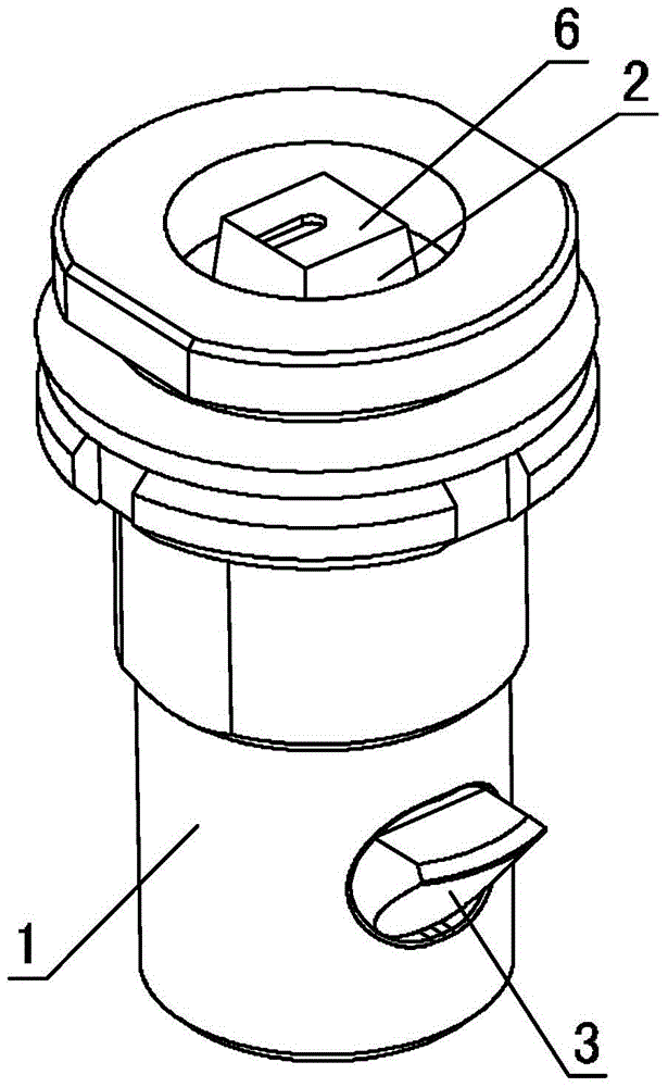
[0040] Example: see attached Figure 1-17 As shown, a safety strike lock includes a lock case 1, a lock core 2 and a dead bolt 3; wherein,

[0041] An assembly hole 4 is vertically provided on the front of the lock case 1 for the penetration of the lock cylinder 2; a deadbolt telescopic hole 5 is vertically provided on the side of the lock case 1 for the penetration of the deadbolt 3 ; Wherein, the bolt telescopic hole 5 communicates with the bottom end of the assembly hole 4;

[0042] The top of the lock core 2 is provided with a switch action part 6 that cooperates with the key, and the bottom end of the lock core 2 is an action head 7, the action head 7 is cam-shaped, and the center of rotation of the action head 7 is located at At the rotating end 8, the center of rotation is the axis of the lock core 2; an elastic locator is arranged vertically outward on the peripheral wall of the lock core 2, corresponding to the elastic locator, the peripheral wall of the assembly hol...


PUM


Abstract

Disclosed is a safety slam lock. The safety slam lock is characterized by comprising a lock case, a lock cylinder and a bolt. An elastic locating piece is arranged on the circumferential wall of the lock cylinder, and three locating blind holes are formed in the lock case to be matched with the elastic locating piece; a cam-shaped action head portion is arranged at the bottom end of the lock cylinder; a groove is formed in the bolt so as to enable the action head portion to be arranged in a swing mode, the groove is pressed through swing of the action head portion and then the bolt is driven to stretch out and draw back; when the action head portion swings to the limits on the two sides, the angle between the center line of the cross section of the action head portion and the stretching direction of the bolt ranges from 0 degree to 10 degrees. Due to the fact that the locating blind holes are matched with the elastic locating piece on the lock cylinder, the action head portion at the bottom of the lock cylinder can be located at the positions with two swing extreme values and an intermediate value, so that three working positions of the lock cylinder in the circumferential direction are formed, namely, a locking state, an unlocking state and a free state. The safety slam lock solves the problem that a conventional slam lock is low in reliability, namely, the phenomena of unlocking and falling tend to happen due to shock, and has the advantages that the working conditions are various, and use is convenient.

Description

technical field [0001] The invention relates to locks used in industries such as transportation and cabinets, in particular to a strike lock used on vehicles such as trains, subways, automobiles, and airplanes. The impact lock is especially suitable for locking the bottom plate of the train carriage. Background technique [0002] A large number of locks are used on trains, subways, automobiles, airplanes and other means of transportation to lock the bottom plate of the compartment or engine room. Since parts on moving objects have higher requirements for locking than stationary objects, reliable locking, convenient use and simple structure have become important criteria for measuring the quality of such locks. In the prior art, ordinary impact locks cannot meet the above requirements for the following reasons: 1. In the locked state, if the head of the dead bolt is subjected to external force or vibration, it will still retract into the lock housing to unlock, which has pot...

Claims


Application Information

Patent Timeline
Patent Type & Authority Patents(China)
IPC IPC(8): E05B83/00E05B85/22E05B85/00
Inventor 阙建章陶喆王金平
Owner SUZHOU D SNAP TECH
Why Eureka
Try Eureka