
A method for identification of transformer saturation under complex inrush conditions

An identification method and transformer technology, applied to electrical components, emergency protection circuit devices, etc., can solve problems such as installation location restrictions, increased cost of current transformers, and prolonging the time for protecting outlets to achieve the effect of preventing misoperation

Active Publication Date: 2017-10-10
STATE GRID CORP OF CHINA +2
View PDF3 Cites 0 Cited by
  • Summary
  • Abstract
  • Description
  • Claims
  • Application Information

AI Technical Summary

Problems solved by technology

[0004] The above method has a certain guiding significance for the identification of transformer saturation, but there are still problems in practical applications: the selection of a current transformer with better performance increases the cost, and is limited by the installation location; in high-voltage power systems, due to long transmission lines Due to the influence of distributed capacitance and series compensation capacitor resonance, the second harmonic content in the fault current may also be relatively large. Strengthening the second harmonic blocking criterion may prolong the protection time of the outlet under fault conditions; increasing the differential protection setting will affect Sensitivity to internal faults; calculation of relative flux linkage accumulation method to determine whether the differential current is caused by transformer saturation based on the number of variance inflection points of the flux accumulation curve within a period of time. prove

Method used


Image

  • A method for identification of transformer saturation under complex inrush conditions
  • A method for identification of transformer saturation under complex inrush conditions
  • A method for identification of transformer saturation under complex inrush conditions

Examples


Embodiment Construction

[0037] The technical solutions in the present invention will be clearly and completely described below in conjunction with the accompanying drawings in the present invention.

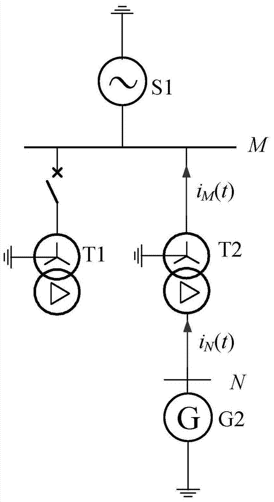
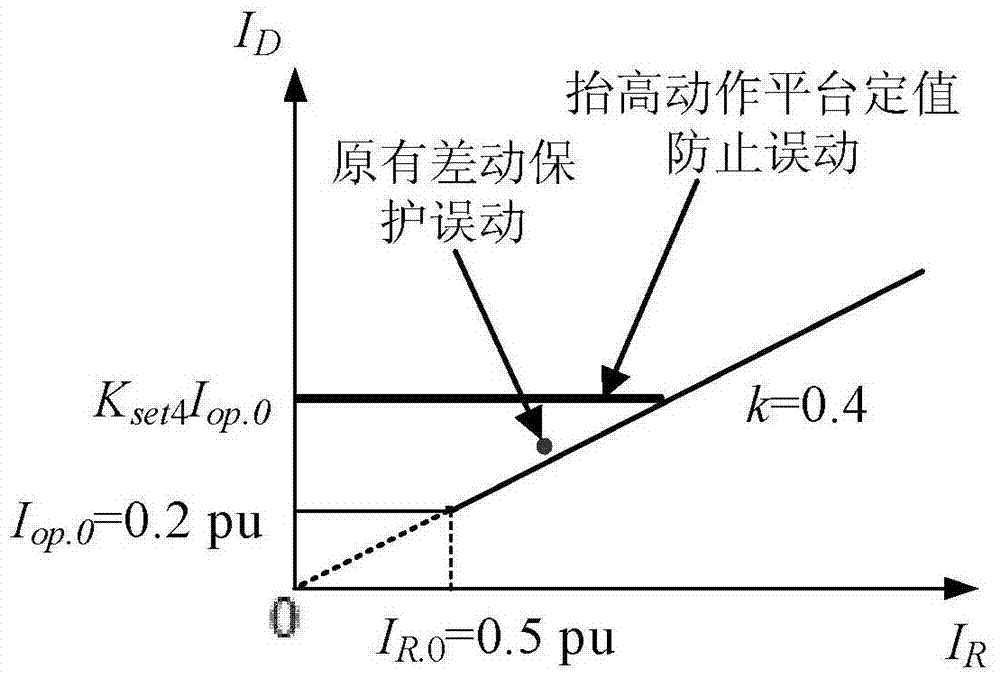
[0038] Such as figure 1 As shown, the transformer T2 forms a differential protection by measuring the current on the N side and the M side, and the reference direction of the measurement current is as follows figure 1 As shown by the arrow in , the action characteristics of the differential protection are as follows figure 2 shown. During the following whole process, keep sampling the three-phase current on both sides of the transformer T2 at equal intervals, and the sampling time interval is T / N 0 , where T is the power frequency cycle of the power grid, N 0 is a positive integer determined according to the sampling rate, and the instantaneous value of the three-phase current on both sides of the transformer T2 is obtained at each sampling moment.

[0039] Please refer to Figure 4 , the identifi...


PUM


Abstract

The invention provides a recognition method for transformer saturation under the condition of complex surge. The recognition method comprises the following steps of (1) reading three-phase current sampling values at the two sides of protected equipment; (2) judging whether transformer-saturation recognition criterion is started according to the read three-phase current sampling values at the two sides of the protected equipment, if the judgment result is yes, starting the transformer-saturation recognition criterion and executing the step (3), or returning the step (1); (3) judging whether the aperiodic component of current becomes lower; (4) judging whether differential protection acts; and (5) carrying out self-adaptive adjustment on a constant value of a differential-protection acting platform. The recognition method provided by the invention has the advantages that TA saturation can be effectively recognized, differential-protection false action caused by TA saturation in the period of complex surge is prevented, the internal fault condition can not be misjudged as TA saturation, and the sensitivity of protection when the internal faults occur is not influenced.

Description

technical field [0001] The invention relates to the technical field of electric power system relay protection, in particular to a method for identifying transformer saturation under complex inrush conditions. Background technique [0002] With the rapid advancement of electric power construction, the power grid has gradually developed into a complex power grid with large scale, complex structure, and flexible operation mode. The complexity and diversity of its transient process puts forward higher requirements for the performance of protective current transformers. The field accident analysis shows that the saturation of the current transformer in the transient process is one of the main reasons for the misoperation of the differential protection. The differential protection is usually the main protection of power system equipment, and its misoperation may cause serious harm to the safety of the equipment itself and the stable operation of the system. [0003] There are man...

Claims


Application Information

Patent Timeline
Patent Type & Authority Patents(China)
IPC IPC(8): H02H7/045
Inventor 张侃君尹项根周友斌张哲夏勇军戚宣威文博廖钊黎恒烜蔡飞陈堃叶庞琪杜镇安雷杨
Owner STATE GRID CORP OF CHINA
Learn More