Method for identifying modeling boundary of sub-synchronous resonance actual system

A technology of subsynchronous resonance and actual system, applied in the field of power system, can solve the problem that the actual system cannot be directly judged at one time, and the strength of the subsynchronous resonance cannot be directly calculated.

Active Publication Date: 2015-04-29
JIANGSU UNIV
View PDF6 Cites 2 Cited by
  • Summary
  • Abstract
  • Description
  • Claims
  • Application Information

AI Technical Summary

Problems solved by technology

[0008] In order to overcome the deficiency that the existing technology cannot directly calculate the strength of each power component in the actual system on t

Method used


Image

  • Method for identifying modeling boundary of sub-synchronous resonance actual system
  • Method for identifying modeling boundary of sub-synchronous resonance actual system
  • Method for identifying modeling boundary of sub-synchronous resonance actual system

Examples


Embodiment

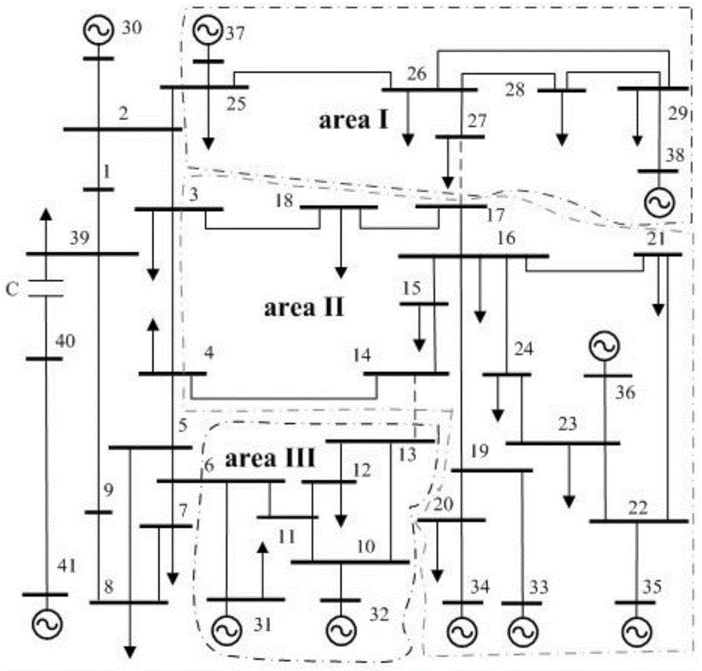
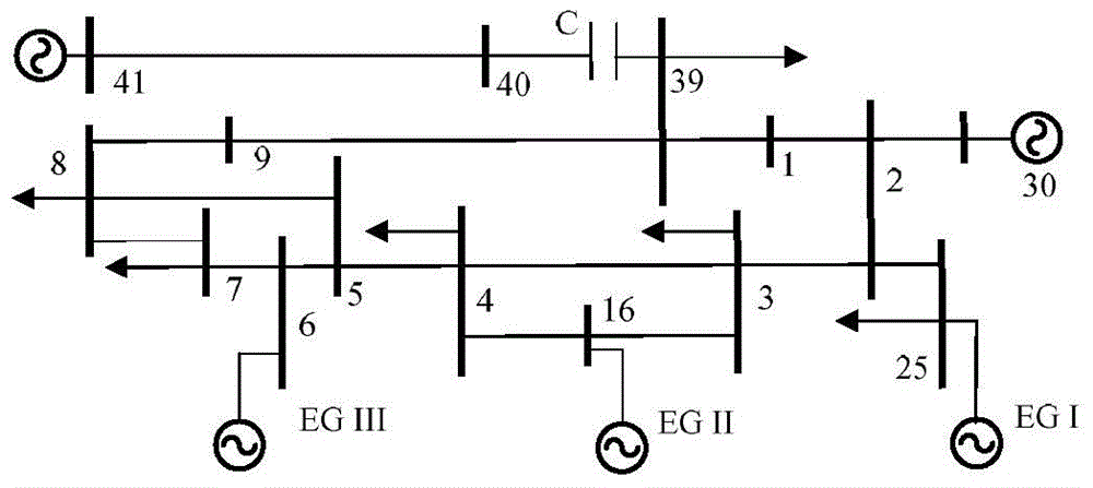
[0044] In this embodiment, the improved New Zealand IEEE10 unit 39-node system model is used for subsynchronous resonance modeling, and two parallel IEEE first benchmark model generator sets are connected at node 41, where the transmission line impedance parameter between nodes 40 and 41 is 0.00112+ j0.03856pu, the impedance between nodes 40 and 39 is 0.02079pu. Focus on the SSR problem of two generators connected at node 41, the modeling method steps are as follows:

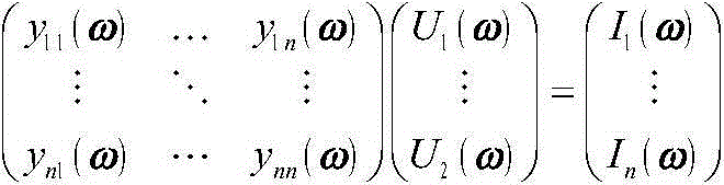
[0045] Step 1: Inject the unit current with a frequency interval of [0, 120] Hz and an interval of 0.0001 Hz into the voltage equation of the system node at the node of the system research unit, and the injection current of other system nodes is 0, and calculate the driving point at the node of the research unit Impedance: Z(ω)=R(ω)+jX(ω)=U, where: ω=2πf is the angular frequency; Z(ω) indicates that when the injected unit current frequency is ω, the node of the research unit looks into the system The equivalent...


PUM


Abstract

The invention discloses a method for identifying modeling boundary of a sub-synchronous resonance actual system. The method comprises the following steps: injecting unit current in a certain frequency range into voltage equations of system nodes at a system study set node, injecting 0 current into other system nodes, by calculating impedance of a driving point, searching for a natural resonant frequency of driving point impedance of the system and a driving point equivalent resistance value under the frequency, then respectively calculating sensitivity factors I1 and I2 of power components; dividing power components in the system into three classes, expanding a study area formed by a first class of power components to the exterior by one node, and determining the sub-synchronous resonance modeling area and a molding boundary of an actual system; determining the specific sub-synchronous resonance boundary of the actual system by defined sub-synchronous resonance frequency sensitivity factors of the power components and impedance sensitivity factors of the power component. The accuracy of identifying the sub-synchronous resonance boundary and the modeling efficiency are improved.

Description

technical field [0001] The invention belongs to the technical field of electric power systems, and in particular relates to a modeling boundary identification method of a subsynchronous resonance actual system. Background technique [0002] A large number of long-distance AC series compensation transmission projects have been put into operation, making subsynchronous oscillation one of the important factors threatening the security of my country's power grid. Many large thermal power plants such as Yimin, Suizhong, Shangdu, Baorixile, Pannan, Jinjie, Tuoketuo, Shenmu, Fugu, and Yangcheng are connected to the system through series compensation transmission lines, and there are relatively large Severe subsynchronous oscillation threat. [0003] In the face of complex large-scale power systems, it is undoubtedly the most accurate method in theory to establish a detailed electromagnetic transient model of the whole system for practical engineering research. However, large-scal...

Claims


Application Information

Patent Timeline
IPC IPC(8): G06F19/00
Inventor 陈武晖董德勇毕天姝
Owner JIANGSU UNIV
Why Eureka
Try Eureka