
A clamping safety device for surgical stapler

A safety device and surgical suture technology, which are applied in surgical fixation nails, medical science, surgical forceps, etc., can solve the problems of unsatisfactory firing safety device design, long unfavorable recovery time for patients, and large incisions for surgical patients, so as to avoid surgical errors. , to ensure the success rate of surgery, the effect of compact structure

Active Publication Date: 2017-01-11
JIANGSU ZIHANG PRECISION HARDWARE
View PDF4 Cites 0 Cited by
  • Summary
  • Abstract
  • Description
  • Claims
  • Application Information

AI Technical Summary

Problems solved by technology

[0003] At present, the cutting and stapling devices are all open-type cutting and stapling devices. The volume of the instruments is relatively large, and the incision of the surgical patient is relatively large, which is unfavorable for the patient's recovery time and increases the pain of the patient.
At present, the design of the firing safety device of the cutting stapler is not ideal, and it is not convenient to use, and it is easy to cause false firing, which affects the success rate of the operation and increases the pain of the patient.

Method used


Image

  • A clamping safety device for surgical stapler
  • A clamping safety device for surgical stapler
  • A clamping safety device for surgical stapler

Examples


Embodiment Construction

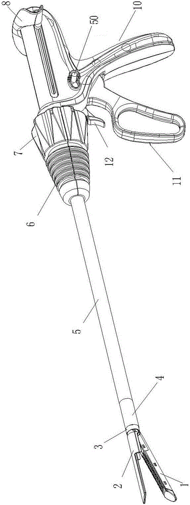
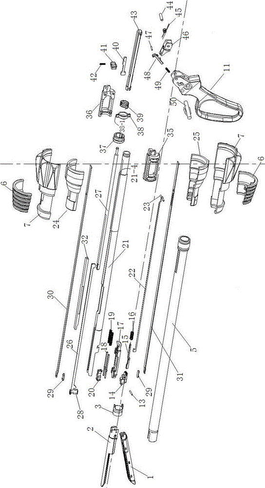
[0070] Refer to attached Figure 1-32 , a clamping safety device for a surgical stapler includes a movable handle 11, a movable handle tension spring 51, a safety button 50, a trigger lever 48, a firing safety block 46, a driving bar 43, a firing positioning rod 27, and a driving bar safety block 41. Driving bar safety driving block 40, positioning guide support tube 21, clamping assembly, blocking ring 38, clamping compression spring 39, driving ring 37, upper connecting bar 30, lower connecting bar 31, connecting piece 29 and locking ring 3.

[0071] The clamping assembly is composed of a left clamping block 35 and a right clamping block 36 .

[0072] The movable handle 11 is installed on the fixed handle 10 , and a movable handle tension spring 51 is arranged in the middle to connect the movable handle 11 and the fixed handle 10 . The upper part of the movable handle 11 is provided with a safety button installation slot 11-2, the top of the movable handle 11 is provided w...


PUM


Abstract

The invention relates to a clamping insurance device for a surgical suture device. The clamping insurance device is a surgical suture device supporting device which applies a linear row on an intra-abdominal tissue and is used for cutting tissues in the linear row suture device simultaneously. The clamping insurance device comprises a movable handle, a movable handle tension spring, an insurance button, a triggering rod, a firing insurance block, a drive bar, a firing positioning rod, a drive bar insurance block, a drive bar insurance drive block, a positioning guide support tube, a clamping component, a blocking ring, a clamping pressure spring, a drive ring, an upper connecting strip, a lower connecting strip, a connecting piece and a locking ring; the movable handle is mounted on a fixed handle, and the movable handle tension spring is arranged in the middle and is connected with the movable handle and the fixed handle; the triggering rod is mounted in a triggering rod mounting groove, and a triggering rod pressure spring is mounted at the lower part of the triggering rod; the drive bar is mounted at the upper part of the fixed handle, and the front end of the drive bar is inserted in the left clamping block and the right clamping block; the positioning guide support tube is mounted in an outer sleeve, and the rear end is mounted in the left clamping block and the right clamping block and is connected with the fixed handle.

Description

technical field [0001] The invention relates to a clamping safety device for a surgical stapler, which is a surgical stapler matching device for applying linear rows on tissue in a cavity and cutting tissue between the linear rows of staplers at the same time. Background technique [0002] During laparoscopic and or endoscopic surgery, the procedure is performed through a small incision in the patient or through a narrow cannula inserted into the wound. In traditional or open procedures, the doctor has direct access to the surgical site. The abdominal operating table offers advantages over open surgery due to its reduced patient trauma, shortened patient recovery period, and significantly lower overall costs. To meet the specific needs of endoscopic and intraperitoneal, endoscopic suturing devices have been developed to allow easier access to the surgical site. Typically, these suturing instruments include an articulating tool member supported at the proximal end of the su...

Claims


Application Information

Patent Timeline
Patent Type & Authority Patents(China)
IPC IPC(8): A61B17/072
CPCA61B17/00234A61B17/072A61B17/29A61B2017/07271
Inventor 王超航
Owner JIANGSU ZIHANG PRECISION HARDWARE
Learn More