Real-time diagnosis system for section of accelerator particle beam

A technology of real-time diagnosis and particle beam, which is applied in the field of image detection system, can solve the problems of fluorescent screen heat dissipation and life-span impact, impact on spectrometer beamline experiment application, large impact and loss, etc., to improve chromatic aberration and imaging quality, and facilitate image collection , The effect of small optical coupling distortion

Active Publication Date: 2015-05-06
DONGGUAN NEUTRON SCI CENT
View PDF4 Cites 12 Cited by
  • Summary
  • Abstract
  • Description
  • Claims
  • Application Information

AI Technical Summary

Problems solved by technology

Due to the cumbersome mechanical retractable device, the traditional fluorescent screen diagnostic system is not convenient to install at a position very close to the front of the target. On the high-power target shooting device, due to the increase of the shielding thickness, it is difficult to extract the optical signal by using the traditional method.
At the same time, the thickness of the traditional fluorescent screen is more than 1mm, the energy deposited by the beam is greater, the heat dissipation and life of the fluorescent screen will be affected, and the impact and loss of the beam are relatively large
The Chinese spallation neutron source facility under construction is a pulsed neutron source user experiment platform based on proton beam targeting. The state of the incident proton beam in front of the target directly affects the properties of the neutron flux and energy spectrum distribution generated by the target, and then Experimental Applications Affecting Spectrometer Beamlines

Method used


Image

  • Real-time diagnosis system for section of accelerator particle beam
  • Real-time diagnosis system for section of accelerator particle beam
  • Real-time diagnosis system for section of accelerator particle beam

Examples


Embodiment Construction

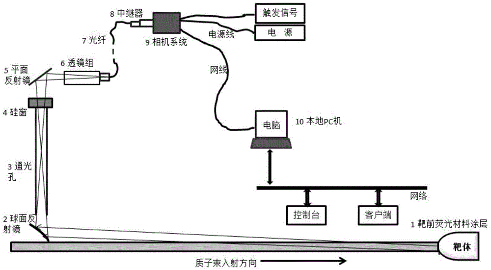
[0024] The invention includes two sets of a prototype and a formal system in the development process, the prototype system is used for the research of the principle and optical path debugging method, and the formal system is used for the diagnosis of the target beam current. Combining the functions of the prototype, the official system and the drawings, the implementation steps of the system are described in detail as follows:

[0025] The length of the proton beam channel between the front window of the target body and the proton beam window is 1987mm, and the upper part of the channel is a thick steel bar + cement shielding block. There is a shield block gap at a height of about 1045mm from the center of the proton beam window. The gap space is about 220mm high, and the horizontal plane is a circular area with a radius of about 338mm, which is mainly used for arranging various pipelines of the target station. The interstitial space continues upwards with thick steel bars + c...


PUM


Abstract

The invention discloses a real-time diagnosis system for a section of an accelerator particle beam. The system comprises an optical imaging system and an image data acqusition and analysis system, wherein a target front window is provided with a fluorescent material coating; the optical imaging system comprises an off-axis reflecting mirror (2), a light through hole (3), a silicon window (4), a reflecting mirror (5) and a focusing imaging lens set (6) in a radiation region; the off-axis reflecting mirror (2) is used for reflecting fluorescence emitted by the fluorescent material coating into the light through hole (3) in an off-axis manner; a light exit end of the light through hole (3) is hermetically connected with the silicon window (4); the light emitted by the silicon window (4) is reflected to the focusing imaging lens set (6) by the reflecting mirror (5); light is output to the image data acqusition and analysis system on the outer side of the radiation region in a coupling manner by the focusing imaging lens set (6). According to the system, on-line diagnosis can be performed on an ion beam within a range which is 2 cm away from a shooting position; the system can be used for real-time monitoring of the shooting situation in the region close to the target and the transverse sectional distribution of the beam.

Description

technical field [0001] The invention relates to the technical field of accelerator beam current diagnosis, in particular to an image detection system for real-time on-line monitoring of beam current targeting status and transverse cross-sectional distribution. The imaging system is installed at the nearest position of the accelerator beam shooting to monitor and record the beam shooting parameters in the near target area in real time, which is convenient for beam adjustment and timely understanding of the operation of the device. Background technique [0002] On the accelerator, parameters such as the cross-sectional distribution and size of the beam are the basis for the measurement of other parameters of the beam, which can reflect the quality of the beam. The monitoring of the beam cross-section parameters near the target position is convenient for the accelerator to adjust and optimize the beam in time. It is helpful for more realistic simulation and calculation of the p...

Claims


Application Information

Patent Timeline
Patent Type & Authority Applications(China)
IPC IPC(8): G01T1/29
Inventor 曾智蓉吴丽萍梁天骄姚思一于全芝闫恒忠周斌
Owner DONGGUAN NEUTRON SCI CENT
Why Eureka
Try Eureka