
Traction device for mandibular impacted wisdom teeth

A technology of impacted wisdom teeth and traction device, applied in medical science, dentistry, orthodontics, etc., can solve the problems of lower lip numbness, long course of treatment, affecting the quality of life of patients, reduce the depth of the gingival pocket, avoid the lower lip Numbness, flexible movement effects

Inactive Publication Date: 2015-05-20
SHANGHAI XUHUI DISTRICT DENTAL CENT
View PDF4 Cites 11 Cited by
  • Summary
  • Abstract
  • Description
  • Claims
  • Application Information

AI Technical Summary

Problems solved by technology

[0002] In oral clinic, pericoronitis of mandibular impacted wisdom teeth is relatively common. If such patients have recurrent pericoronitis, extraction of the impacted wisdom tooth is often considered. However, if the mandibular wisdom tooth to be extracted is closely adjacent to the inferior alveolar canal, direct Extraction of impacted wisdom teeth may damage the alveolar nerve canal, cause lower lip numbness, and significantly affect the patient's quality of life
A better way to solve this problem is to combine orthodontic treatment first, move the wisdom teeth away from the inferior alveolar canal through orthodontic traction, and then extract them, but the existing orthodontic methods have narrow indications and a long course of treatment

Method used


Image

  • Traction device for mandibular impacted wisdom teeth
  • Traction device for mandibular impacted wisdom teeth
  • Traction device for mandibular impacted wisdom teeth

Examples


Embodiment Construction

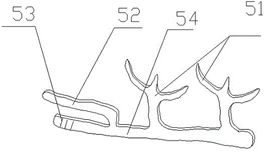
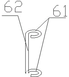
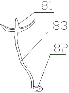
[0020] combine Figure 1-4 The present invention is described.

[0021] like Figure 4 As shown, the first molar 1, the second molar 2 and the impacted wisdom tooth 3 are all located on the same side of the mandible, and the impacted wisdom tooth 3 is closely adjacent to the inferior alveolar canal. The same side here refers to the left or right side.

[0022] The mandibular impacted wisdom tooth traction device includes a bracket 5 for fixing on the lingual side of the first molar 1 and the second molar 2, a first retaining part 6 for fixing on the coronal side of the impacted wisdom tooth 3, and a bracket for fixing on the lingual side of the impacted wisdom tooth 3. The second retaining part on the buccal side of a molar 1, the traction part whose two ends are respectively connected with the bracket 5 and the first retaining part 6 . The bracket 5 includes a rod-shaped main body 54, a connecting head 51, a connecting rod and a cross bar 52. The rod-shaped main body corre...


PUM


Abstract

The invention provides a traction device for mandibular impacted wisdom teeth, which relates to the field of orthodontics. The device comprises a bracket, a first retention part, a second retention part and a traction part, wherein the bracket is used for being fixed on the lingual sides of mandibular first and second molars on the same side of a mandibular impacted wisdom tooth, the first retention part is used for being fixed on the crown side of the mandibular impacted wisdom tooth, the second retention part is used for being fixed on the buccal side of the mandibular impacted wisdom tooth, and the two ends of the traction part are respectively connected with the bracket and the first retention part; and the bracket comprises a rod-shaped main body, connecting heads, a connecting rod and a cross rod, the connecting heads are respectively arranged at the positions on the rod-shaped main body and corresponding to the mandibular first and second molars, a groove and the cross rod are arranged at the positions on the rod-shaped main body and corresponding to the mandibular impacted wisdom tooth, the cross rod and the rod-shaped main body are parallel to each other and are located on the occlusion side of the rod-shaped main body, and the cross rod is connected with the rod-shaped main body by the connecting rod. The traction device provided by the invention can flexibly adjust the traction direction of an impacted wisdom tooth, and effectively draw the impacted wisdom tooth to separate from an alveolar nerve canal in a relatively short period of time so as to facilitate subsequent tooth extraction treatment.

Description

technical field [0001] The invention relates to the field of orthodontic instruments, in particular to a traction device for mandibular impacted wisdom teeth. Background technique [0002] In oral clinic, pericoronitis of mandibular impacted wisdom teeth is relatively common. If such patients have recurrent pericoronitis, extraction of the impacted wisdom tooth is often considered. However, if the mandibular wisdom tooth to be extracted is closely adjacent to the inferior alveolar canal, direct The extraction of impacted wisdom teeth may damage the alveolar nerve canal, cause lower lip numbness, and significantly affect the quality of life of patients. A better way to solve this problem is to combine orthodontic treatment first, and remove the wisdom teeth from the inferior alveolar canal through orthodontic traction, and then extract them. However, the existing orthodontic methods have narrow indications and a long course of treatment. Contents of the invention [0003] ...

Claims


Application Information

Patent Timeline
IPC IPC(8): A61C7/00
Inventor 马晓晴秦飞周建华徐培成钱文昊
Owner SHANGHAI XUHUI DISTRICT DENTAL CENT
Learn More