

Recording device
A recording device and equipment technology, applied in the direction of printing device, printing, etc.
- Summary
- Abstract
- Description
- Claims
- Application Information
AI Technical Summary
Problems solved by technology
Method used
Image

Examples
no. 1 Embodiment approach
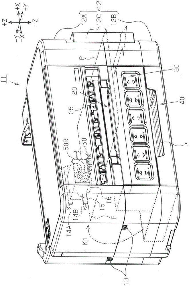
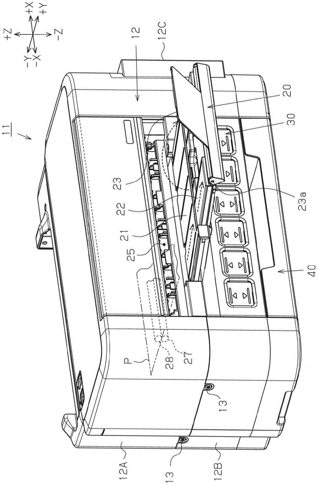
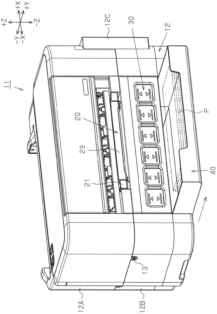
[0051] Such as figure 1 As shown, a printer 11 as an example of a recording device has a printer body 12 having a substantially rectangular parallelepiped shape as the device body. A plurality of cases such as the lower case 12B located on the gravity direction (−Z direction) side and the cover case 12C described later are configured. Furthermore, the housings 12A, 12B, and 12C are connected and fixed to each other by screws 13 or the like. In addition, the printer 11 includes a liquid ejection head 16 , a discharge unit 20 for discharging printing paper P, a liquid container 30 capable of containing ink supplied to the liquid ejection head 16 , and a liquid container 30 capable of containing ink supplied to the liquid ejection head 16 in the printer main body 12 . The supply box 40 of printing paper P.
[0052] The liquid ejection head 16 is located on the side opposite to the gravitational direction (+Z direction) in the vertical direction with respect to the discharge uni...
no. 2 Embodiment approach
[0113] The printer 11 of the second embodiment has a structure in which, in the above-mentioned first embodiment, the liquid recovery unit 60 (liquid storage unit 30 ) is provided below the supply cassette 40 instead of between the discharge unit 20 and the supply cassette 40 . between. A printer 11 according to the second embodiment will be described with reference to the drawings. In addition, in the drawings referred to here, the same reference numerals are assigned to the same components as those of the above-mentioned first embodiment, and description thereof will be omitted.
[0114] Such as Figure 10As shown, in the printer 11 of the second embodiment, the supply cassette 40 is disposed above the lower casing 12B of the printer main body 12, and the liquid container 30 and the liquid recovery portion 60 overlap the supply cassette 40 in the vertical direction. It is arranged below the supply box 40 (-Z direction) in a manner. Therefore, the storage unit 32 for housi...
no. 3 Embodiment approach
[0120] The printer 11 according to the third embodiment has a configuration in which the liquid recovery unit 60 is provided on the supply cassette 40 in the above-mentioned first embodiment. An example of the third embodiment will be described with reference to the drawings. In addition, in the drawings referred to here, the same reference numerals are assigned to the same components as those of the above-mentioned first embodiment, and description thereof will be omitted.
[0121] Such as Figure 12 As shown, in the printer 11 according to the third embodiment, the supply cartridge 40 is equipped so that it can be inserted and removed with respect to the lower case 12B located on the side of the gravity direction (-Z direction) in the vertical direction, and recovers the liquid from the A liquid recovery unit 60 (housing 61 ) for ink discharged from the ejection head 16 is provided in the supply cartridge 40 .
[0122] In the present embodiment, the liquid recovery unit 60...
PUM
 Abstract
Description
Claims
Application Information