Electrical Zero Force Plug Connector

A plug-in connector, zero-force technology, applied in the direction of connection, connecting device components, circuits, etc., can solve problems such as inability to ensure locking connection

Active Publication Date: 2016-10-12
KOSTAL KONTAKT SYST
View PDF5 Cites 0 Cited by
  • Summary
  • Abstract
  • Description
  • Claims
  • Application Information

AI Technical Summary

Problems solved by technology

Therefore, it cannot be ensured that the locking connection between the enclosing housing and the joint set is also produced when the clamping sleeve is moved, or vice versa, i.e. moves on the tube contact until it reaches its final position

Method used


Image

  • Electrical Zero Force Plug Connector
  • Electrical Zero Force Plug Connector
  • Electrical Zero Force Plug Connector

Examples


Embodiment Construction

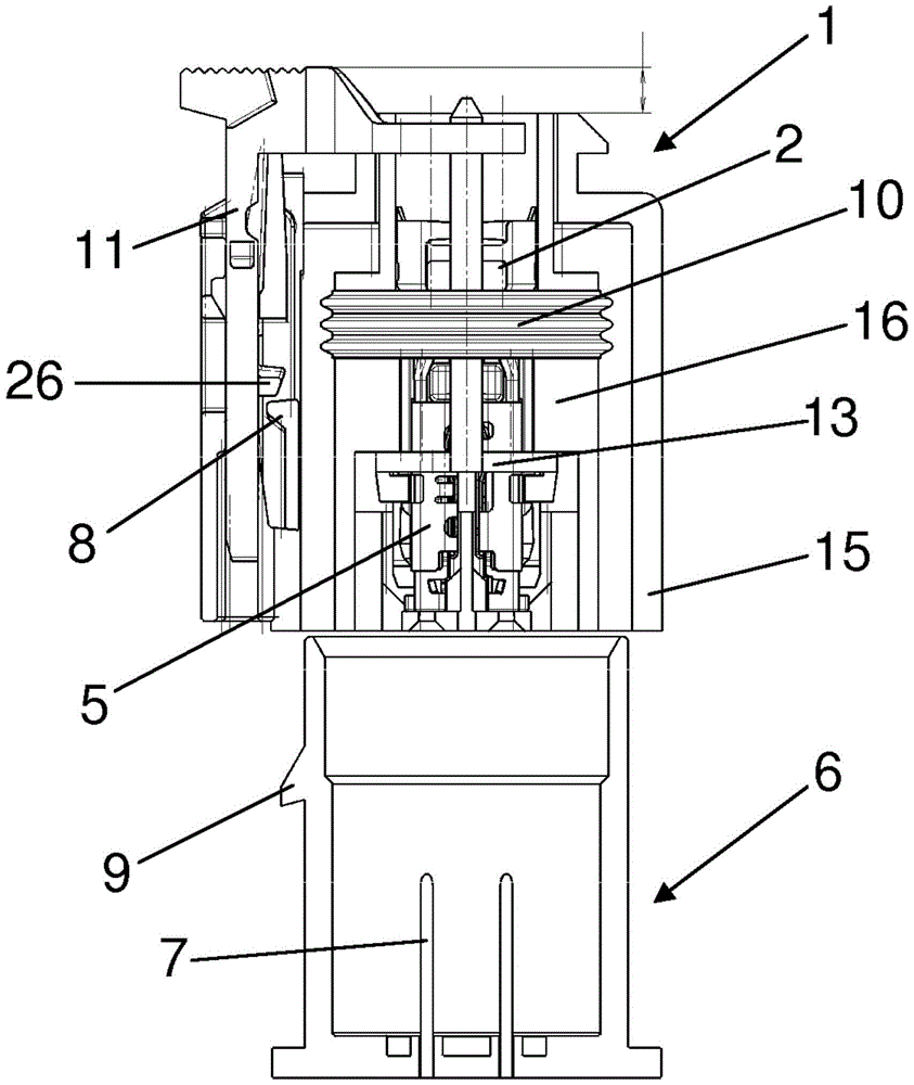
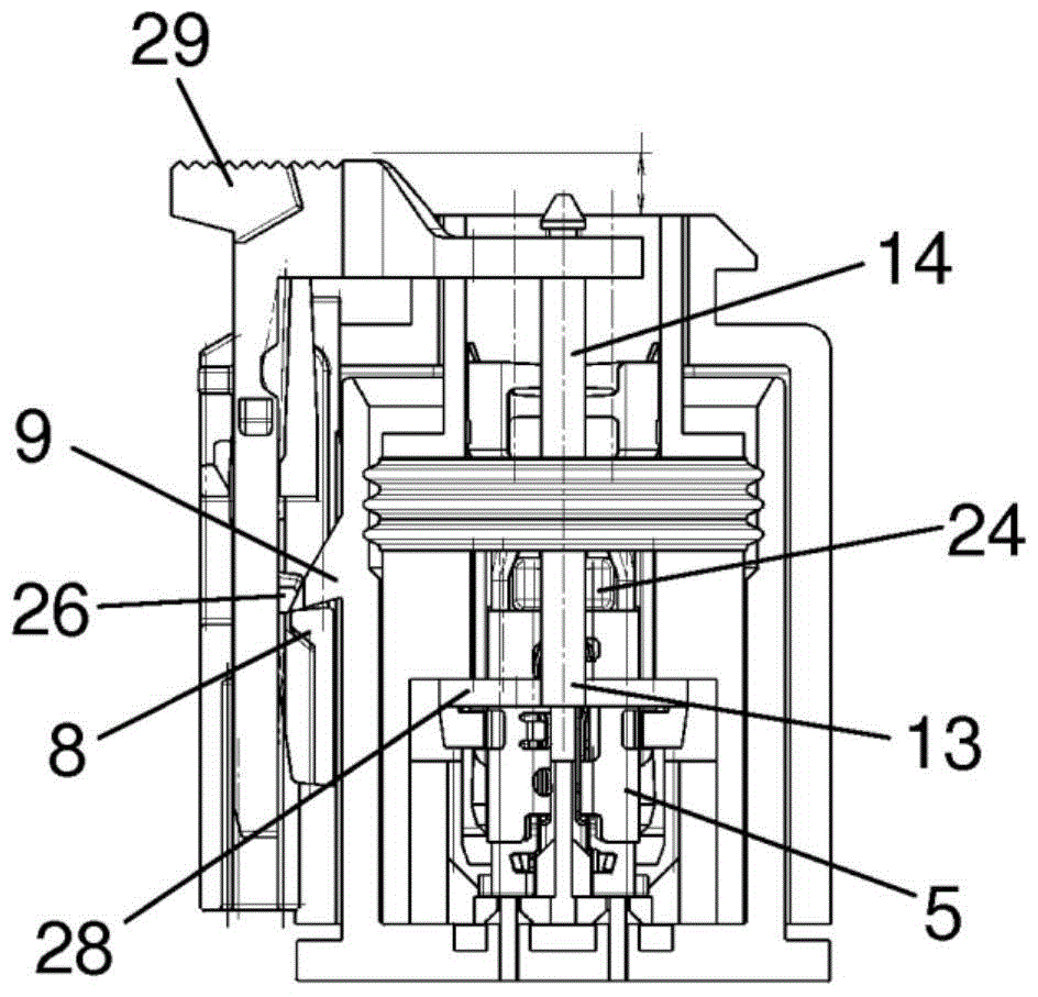
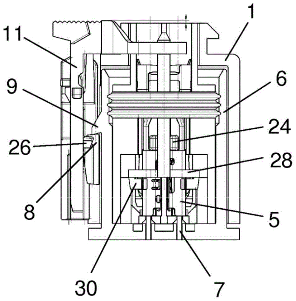
[0018] exist figure 1 shows two interconnectable plug connector parts 1 , 6 of the zero-force plug connector according to the invention in the still unconnected state. The plug connector parts 1 , 6 are also referred to here, in particular, as plug socket housing 1 and socket 6 .

[0019] The plug socket housing 1 consists of an outer enveloping housing 15 and an inner contact carrier 16, which can be embodied either in one piece or as separate parts connected to each other, and can be clearly defined in the Figure 5 seen in. The contact carrier 16 has a plurality of tubular receptacles 25 into which the bushing contacts 2 made of metal are inserted.

[0020] As already described in DE 10 2005 040 952 A1, Figure 7 The bushing contact 2 is shown as a separate component in two views a) and b). The bushing contact 2 is formed by a metallic base body 4 which is connected to an electrical line 22 . The line 22 has an electrical conductor 17 which is electrically and mechanic...


PUM


Abstract

The invention describes an electrical zero-force plug-in connector with: a plug-in sleeve housing having a housing for a plurality of sleeve contacts; a joint set, The joint set has pins for contact parts of the bushings, wherein the bushing contacts each have a base body forming a contact lug and a clamping sleeve movable relative to the base body, wherein the clamping sleeve is opposite When the base body moves, the clamping sleeve presses the contact piece onto the pin of the complete joint, wherein the housing of the sleeve has an elastic locking hook, and the locking hook is connected between the housing of the sleeve and the joint. locked with the lock nose of the complete joint after combination, and wherein the socket housing has a sealing element which abuts against the inner wall of the complete joint after the socket housing is combined with the complete joint, Wherein, a lock bolt is provided on the socket sleeve housing, and the lock bolt can move relative to the socket sleeve housing after the socket sleeve shell and the complete joint are combined, and after the movement, The locking connection of the locking hook and the locking nose is locked, and the locking bolt is connected to a sliding block which is guided through at least one recess of the sealing element and is coupled to the clamping sleeve, and moves the sliding block along with it when moving.

Description

technical field [0001] The invention relates to an electrical zero-force plug-in connector with: a plug-in bushing housing having a housing for several bushing contacts; a joint set, The joint set has pins for contact parts of the bushings, wherein the bushing contacts each have a base body forming a contact lug and a clamping sleeve movable relative to the base body, wherein the clamping sleeve is opposite When the base body moves, the clamping sleeve presses the contact piece onto the pin of the complete joint, wherein the housing of the sleeve has an elastic locking hook, and the locking hook is connected between the housing of the sleeve and the joint. After assembly, it is locked with the locking nose of the joint set, and wherein the plug-in sleeve housing has a sealing element, which bears against the inner wall of the joint set after the plug-in sleeve housing is combined with the joint set. Background technique [0002] Such an electrical zero-force plug connector ...

Claims


Application Information

Patent Timeline
Patent Type & Authority Patents(China)
IPC IPC(8): H01R13/193H01R13/627H01R13/639
CPCH01R13/193H01R13/6271H01R13/639
Inventor 阿图尔·斯沃博达
Owner KOSTAL KONTAKT SYST
Why Eureka
Try Eureka