Bionic step element

A ladder and component technology, applied in the field of integral die-casting aluminum parts, can solve the problems of lack of commercial vitality and a lot of time

Pending Publication Date: 2017-06-27
GF CASTING SOLUTIONS (SUZHOU) CO LTD +3
View PDF9 Cites 0 Cited by
  • Summary
  • Abstract
  • Description
  • Claims
  • Application Information

AI Technical Summary

Problems solved by technology

The skeleton of the steps is further formed from separate parts which have to be fitted together which takes a lot of time which is not commercially viable for the large number of steps required for escalators

Method used


Image

  • Bionic step element
  • Bionic step element
  • Bionic step element

Examples


Embodiment Construction

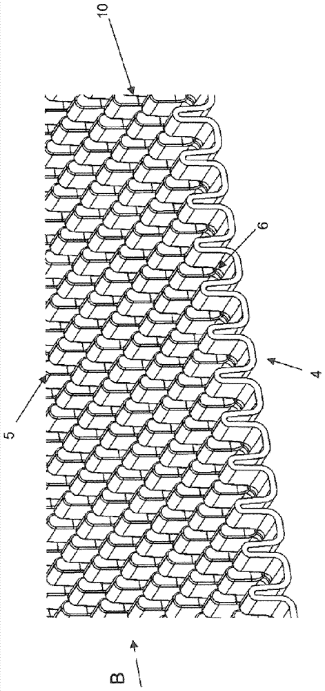
[0057] figure 1 A three-dimensional view of a step element 1 for an escalator is shown. However the invention is equally applicable to the step elements of moving walks, even though these are not shown in the figures.

[0058]The stepped element 1 is configured as a one-piece die-cast aluminum part, whereby expensive assembly processes for the stepped element 1 can be avoided. The ladder element 1 comprises a ladder element skeleton 2, preferably formed by longitudinal and transverse stringers and ribs. The stepped element skeleton 2 is configured according to the desired use. The step element 1 for moving walkways and for escalators comprises a step element skeleton 2 of this type, wherein the skeleton 2 has the task of passing through completely rigid step elements 1 or The ladder element skeleton 2 forms a moving system. All ladder element skeletons 2 thus have to fulfill the same task, and the exact path and exact placement of the longitudinal and transverse webs and r...


PUM


Abstract

The invention relates to a step element for an escalator or for a moving walkway, wherein the step element is configured as a one-piece die-cast aluminium part, comprising a step element skeleton and a step plate, wherein the step plate has a step profile, wherein the step profile has webs and grooves running in the travelling direction, wherein the webs are formed by two web arms running practically parallel to one another and by a connecting web face and the grooves run between the webs which are arranged in a row alongside one another.

Description

technical field [0001] The invention relates to a step element for an escalator or moving walk and a method for its manufacture, wherein the step element is configured as a one-piece die-cast aluminum part comprising a step element skeleton and a step plate, wherein the step plate has a stepped profile , where the stepped profile includes webs and grooves extending in the direction of travel. Background technique [0002] Movement systems such as escalators or moving walks have a plurality of step elements connected to one another by drive chains. [0003] EP 2 173 652 B1 discloses a stepped element which is similarly produced using a pressurized die-casting process and on which strips are mounted. [0004] A disadvantage of this stepped element is the high weight of the stepped element, since the web of the stepped plate has a solid construction and extends continuously, which also requires a large amount of material. [0005] GB 2 216 825 A shows a step with a step plate...

Claims


Application Information

Patent Timeline
Patent Type & Authority Applications(China)
IPC IPC(8): B66B23/12
CPCB66B23/12B22D17/00B22D25/02B66B21/02B66B21/10B66B23/10
Inventor R.库佩施米德D.马尼格U.克雷扎雷克M.索查
Owner GF CASTING SOLUTIONS (SUZHOU) CO LTD
Why Eureka
Try Eureka