Automatic lubricating device

An automatic lubrication and oil cylinder technology, applied in the direction of engine lubrication, engine components, mechanical equipment, etc., can solve the problems of low standardization of operation, poor lubrication continuity, equipment failure, etc., achieve wide application range, solve lubrication, and low manufacturing cost Effect

Inactive Publication Date: 2015-06-17
SHANDONG IRON & STEEL CO LTD
View PDF7 Cites 9 Cited by
  • Summary
  • Abstract
  • Description
  • Claims
  • Application Information

AI Technical Summary

Problems solved by technology

[0002] At present, traditional lubricating devices are often driven by motors or manually lubricated, especially for some reciprocating rotating parts (such as universal couplings, etc.) Poor continuity and low standardization of operation, especially in some production lines that use a large number of reciprocating rotating parts, traditional lubrication methods cannot meet the needs of on-site equipment maintenance, and often cause equipment failure due to lack of lubrication

Method used


Image

  • Automatic lubricating device
  • Automatic lubricating device

Examples


Embodiment Construction

[0014] The present invention will be further described below in conjunction with the accompanying drawings and specific embodiments.

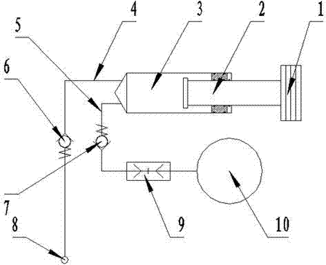
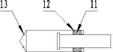
[0015] As shown in the figure: an automatic lubricating device, including an inertial weight 1, a piston 2, an oil cylinder 3, an oil storage bag 10 and a pipeline connecting various components, the inertial weight 1 is connected to the piston 2, and the piston 2 Installed in the oil cylinder 3, it can do axial push-pull movement in the oil cylinder 3. The oil cylinder 3 is connected to the oil filling pipeline 4 and the oil replenishing pipeline 5. The oil filling pipeline 4 is connected to the equipment that needs to be lubricated through the oil filling joint 8 , the oil replenishment pipeline 5 is connected with the oil storage bag 10 through the quick connector group 9 .

[0016] Further, the inertial weight 1 is composed of a plurality of weight blocks, the number of weights can be increased or decreased according to the acceleration of t...


PUM


Abstract

The invention discloses an automatic lubricating device. The automatic lubricating device comprises an inertia weight, a piston, an oil cylinder, an oil storage bag and pipes connecting all the components, wherein the inertia weight is connected with the piston, the piston is arranged in the oil cylinder and can do push and pull movement in the axis direction in the oil cylinder, the oil cylinder is connected with an oil injection pipe and an oil supplementation pipe, the oil injection pipe is connected with equipment needing lubricating through an oil injection connector, and the oil supplementation pipeline is connected with the oil storage bag through a rapid connector set. All the components are fixed, and the automatic lubricating device is installed on the surface of a reciprocating rotary component needing lubricating as a whole. The automatic lubricating device converts continuously changing acceleration in the reciprocating rotary movement into the power source of the automatic lubricating device, in the rotary process of the components, lubricating grease is pumped into the oil cylinder from the oil storage bag and then added to the lubricating point, and therefore oil injection operation is finished, and lubrication on the reciprocating rotary component in a non-stop state is realized.

Description

technical field [0001] The invention belongs to the technical field of machinery, and in particular relates to an automatic lubricating device for reciprocating rotating parts. Background technique [0002] At present, traditional lubricating devices are often driven by motors or manually lubricated, especially for some reciprocating rotating parts (such as universal couplings, etc.) Poor continuity and low degree of operation standardization, especially in some production lines that use a large number of reciprocating rotating parts, traditional lubrication methods cannot meet the needs of on-site equipment maintenance, and often cause equipment failures due to lack of lubrication. Contents of the invention [0003] In view of the deficiencies in the prior art, the object of the present invention is to provide an automatic lubrication device for reciprocating rotating parts, which can lubricate the reciprocating rotating parts without stopping the machine. [0004] In or...

Claims


Application Information

Patent Timeline
Patent Type & Authority Applications(China)
IPC IPC(8): F16N11/00
Inventor 冯攀张令华李刚田田成宋洪林张子义
Owner SHANDONG IRON & STEEL CO LTD
Why Eureka
Try Eureka