
Reaction chamber positioning structure and reaction chamber

A technology for positioning structure and reaction chamber, applied in the field of reaction chamber, can solve problems such as difficult positioning, achieve the effects of simple and reasonable structure design, increase height, improve accuracy and efficiency

Active Publication Date: 2015-07-01
BEIJING NAURA MICROELECTRONICS EQUIP CO LTD
View PDF7 Cites 1 Cited by
  • Summary
  • Abstract
  • Description
  • Claims
  • Application Information

AI Technical Summary

Problems solved by technology

[0004] Based on this, it is necessary to provide a reaction chamber positioning structure that can be easily positioned during installation and a reaction chamber containing the above reaction chamber positioning structure for the problems of difficult positioning of the reaction chamber during assembly.

Method used


Image

  • Reaction chamber positioning structure and reaction chamber
  • Reaction chamber positioning structure and reaction chamber
  • Reaction chamber positioning structure and reaction chamber

Examples


Embodiment Construction

[0034] In order to make the object, technical solution and advantages of the present invention more clear, the reaction chamber positioning structure and the reaction chamber of the present invention will be further described in detail through the following examples and in conjunction with the accompanying drawings. It should be understood that the specific embodiments described here are only used to explain the present invention, not to limit the present invention.

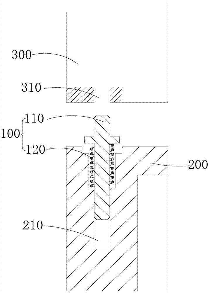
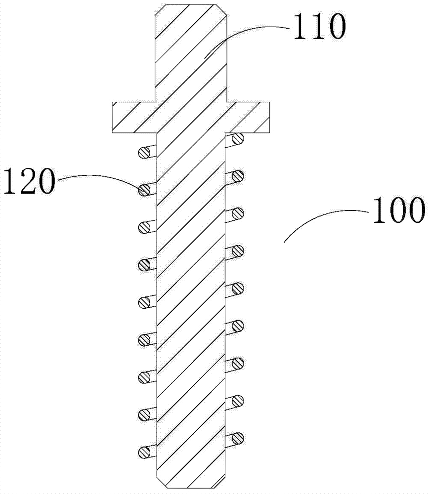
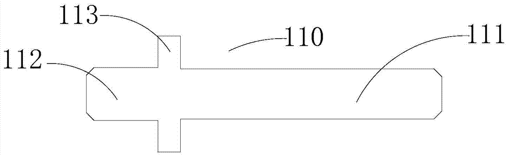
[0035] see Figure 1 to Figure 5 , the reaction chamber of the present invention includes a reaction chamber 200, an upper cover 300, a reaction chamber positioning structure 100 and a guide rail (not shown), the reaction chamber 200 matches the upper cover 300, one end of the guide rail is connected with the reaction chamber 200, and the guide rail The other end is connected with the upper cover 300, and the upper cover 300 moves up and down along the guide rail. The reaction chamber 200 and the upper cover 300...


PUM


Abstract

The invention provides a reaction chamber positioning structure and a reaction chamber. The reaction chamber positioning structure facilitates positioning and installation of an upper cover of the reaction chamber and a reaction cavity and comprises a positioning pin and a spring, wherein a first positioning hole is formed in the reaction cavity, a second positioning hole is formed in the upper cover, the positioning pin is provided with a shaft shoulder for limiting the spring, the spring is arranged on the outer side of one end of the positioning pin in a sleeving mode and installed in the first positioning hole formed in the reaction cavity, the spring is compressed after the second positioning hole formed in the upper cover is aligned to the other end of the positioning pin, and the other end of the positioning pin is inserted into the second positioning hole for positioning. The reaction chamber comprises the reaction chamber positioning structure. The reaction chamber positioning structure and the reaction chamber are simple and reasonable in structural design, the height of the positioning pin is increased through matching of the spring and the positioning pin, and the upper cover and reaction chamber assembling accuracy and efficiency are improved.

Description

technical field [0001] The present invention relates to semiconductor equipment, in particular to a reaction chamber positioning structure applied to a process module of semiconductor equipment, and a reaction chamber containing the above reaction chamber positioning structure. Background technique [0002] At present, when maintaining the interior of the reaction chamber of the reaction chamber, it is necessary to remove the upper cover so as to align the internal parts for wiping or replacement. After the maintenance of the reaction chamber is completed, the upper cover (i.e. the box cover) needs to be reset. When the cover is closed, the positioning pins of the reaction chamber are inserted into the corresponding pin holes of the upper cover. Due to the limitation of space, the height of the positioning pin of the reaction chamber is relatively low, generally about 25mm. When the upper cover moves down to match the positioning pin of the reaction chamber, the distance bet...

Claims


Application Information

Patent Timeline
IPC IPC(8): H01L21/67
CPCH01L21/67011H01L21/68
Inventor 郭峰
Owner BEIJING NAURA MICROELECTRONICS EQUIP CO LTD
Features
  • Generate Ideas
  • Intellectual Property
  • Life Sciences
  • Materials
  • Tech Scout
  • Unparalleled Data Quality
  • Higher Quality Content
  • 60% Fewer Hallucinations
Learn More