Calculation Method of Generating Unit Output in Power System Restoration
A power system recovery and generator set technology, applied in the field of power systems, can solve the problems of not considering whether the power flow of the power generation system is convergent, not considering the output characteristics of the generator, and limiting the active power of the generator, so as to shorten the adjustment time and improve the recovery efficiency , the effect of accelerating recovery
- Summary
- Abstract
- Description
- Claims
- Application Information
AI Technical Summary
Problems solved by technology
Method used
Image
Examples
Embodiment 1
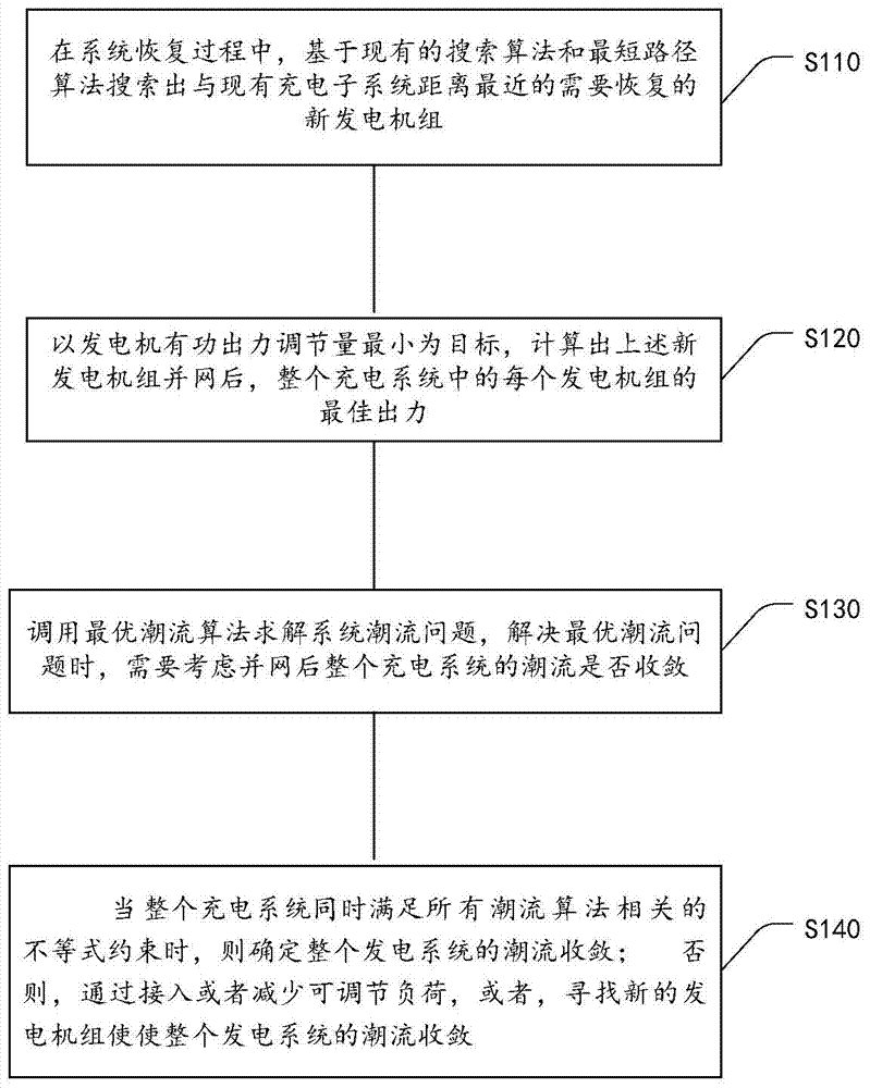
[0051] The processing flow of a method for calculating the power output of generator sets in power system recovery provided by the embodiment of the present invention is as follows: figure 1 As shown, the following processing steps are included:
[0052] Step S110 , in the process of system recovery, for the charging subsystem composed of the restored part of the power grid, search for all the units adjacent to the above-mentioned charging subsystem based on the existing search algorithm. Then, a new generating set that needs to be restored in the next stage closest to the charging subsystem is found from all the above-mentioned generating sets through the shortest path algorithm, and the new generating set is connected to the grid.
[0053] Step S120 , with the goal of minimizing the adjusted amount of active power output of the generators, calculate the optimal output of each generator set in the entire charging system after the above-mentioned new generator sets are connect...
Embodiment 2
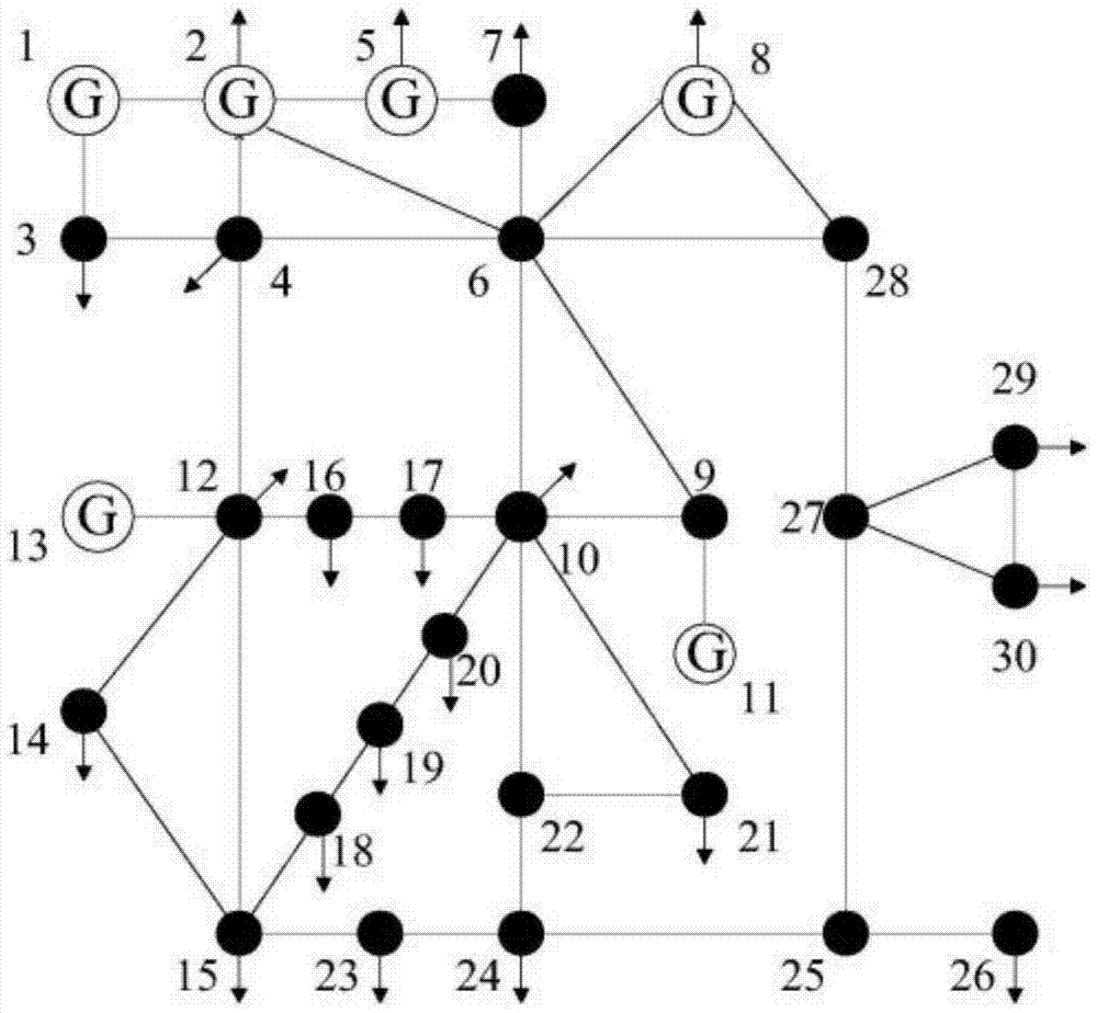
[0083] In order to test the scheme proposed by the embodiment of the present invention, a schematic diagram of a network of a generating set system using IEEE (Institute of Electrical and Electronics Engineers, Institute of Electrical and Electronics Engineers)-30 nodes provided by this embodiment is as follows figure 2 said, figure 2 It contains 30 nodes, 6 generators, 4 transformers and 37 transmission lines. The parameters of each generator node are shown in Table 1.
[0084] Table 1 IEEE-30 node system generator parameters
[0085]
[0086] Nodes 1, 2, 5, 8, 11 and 13 are generator nodes, and the corresponding generator numbers are 1, 2, 3, 4, 5 and 6; branches 4-12, 6-9, 6-10 and 27-28 are transformer branches, and other branches are transmission lines. Engine No. 1 at node 1 is used as the black start power supply, and the rest of the generators are the target generators. No. 1 generator is used as the black start power supply, and No. 2-6 generators are the target...
PUM
 Abstract
Description
Claims
Application Information
 - R&D
- Intellectual Property
- Life Sciences
- Materials
- Tech Scout
- Unparalleled Data Quality
- Higher Quality Content
- 60% Fewer Hallucinations
Browse by: Latest US Patents, China's latest patents, Technical Efficacy Thesaurus, Application Domain, Technology Topic, Popular Technical Reports.
© 2025 PatSnap. All rights reserved.Legal|Privacy policy|Modern Slavery Act Transparency Statement|Sitemap|About US| Contact US: help@patsnap.com


