Contactless intelligent self-service license photographing equipment and method
A shooting device and touch-free technology, which is applied to instrument-controlled coin-operated equipment, coin-operated equipment for distributing discrete items, and TVs, etc., which can solve the problem of blocking the user's line of sight, increasing the difficulty of handling and transportation costs, and causing user anxiety and other issues, to achieve the effect of expanding the shooting area space, not easy to secondary damage, and low transportation cost
- Summary
- Abstract
- Description
- Claims
- Application Information
AI Technical Summary
Problems solved by technology
Method used
Image
Examples
Embodiment 1
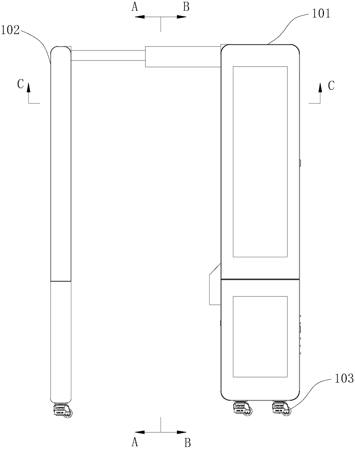
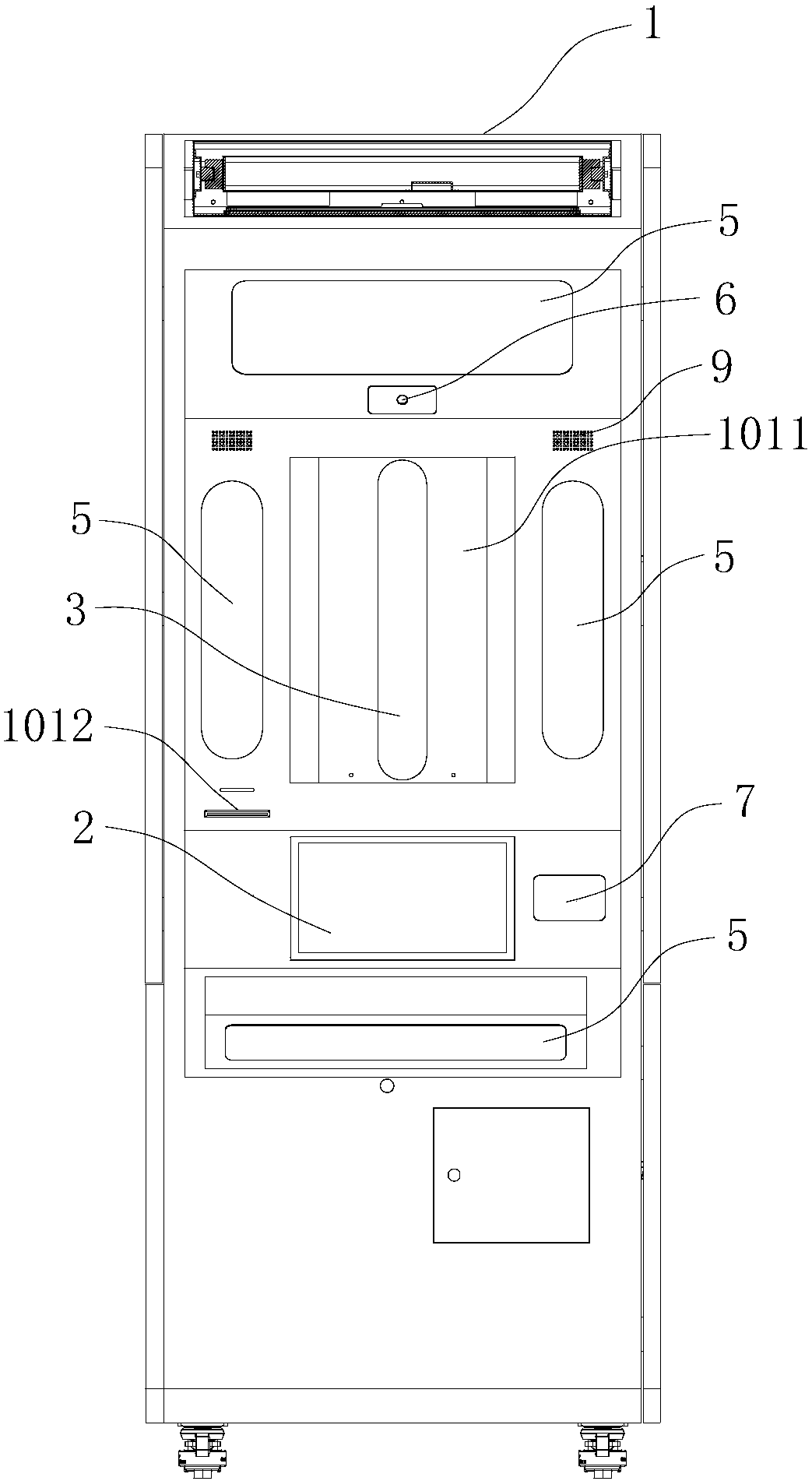
[0069] Such as Figure 1 to Figure 5 As shown, the present embodiment provides a touch-free intelligent self-service license photographing device, which includes a chassis 1, an input / output module 2, a camera module 3 and an intelligent module 4, and the input / output module 2 is arranged on the chassis 1 Above, the camera module 3 and the intelligent module 4 are arranged in the case 1, and the intelligent module 4 is connected with the input / output module 2 and the camera module 3 respectively.
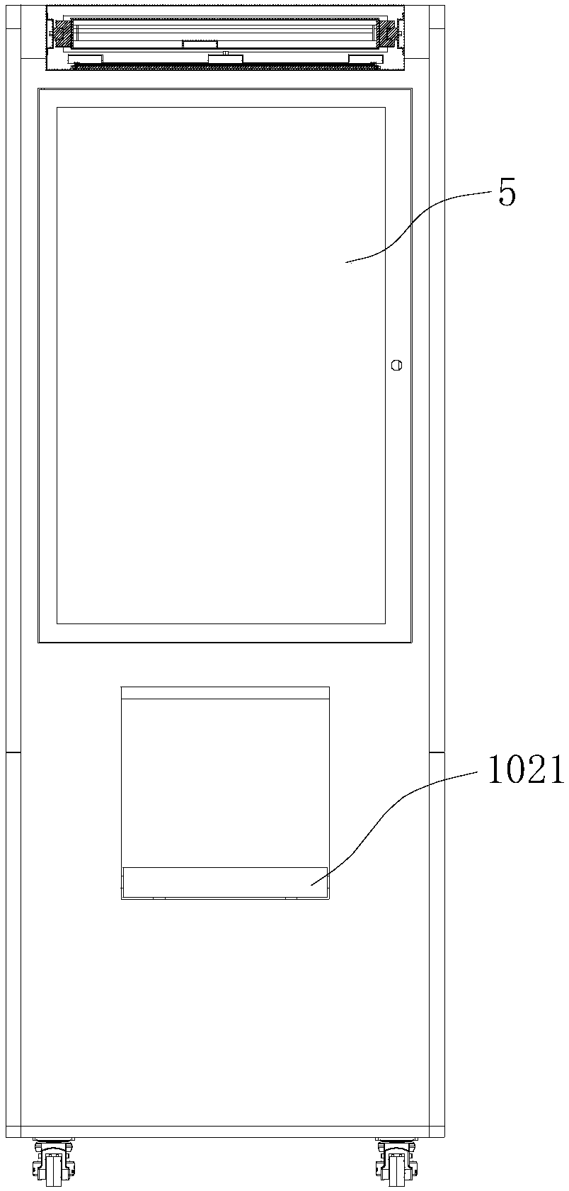
[0070] The chassis 1 includes a fixed module 101 and a telescopic module 102, the fixed module 101 and the telescopic module 102 are connected by a telescopic part, and a seat 1021 is arranged inside the backboard of the telescopic module 102, and the seat 1021 is a foldable seat. The chair can be received in the backboard or turned outward; the bottom of the cabinet 1 is provided with universal wheels 103, which is convenient for the operator to move the whole device.
[0071] In ...
Embodiment 2
[0118] The main features of this embodiment are: the telescopic part is a two-section slide rail, and when the slide rail shrinks, the Figure 12 As shown in , the device is for ordinary users to take pictures at this time, and when the slide rail is stretched, it looks like Figure 13 As shown in , the device is for wheelchair users to take photos at this time, and the usage status of wheelchair users is as follows: Figure 14 As shown, the retractable module 102 is stretched to the furthest distance from the fixed module 101 (that is, pulled out one step away from the fixed module 101), and the seat 1021 on the retractable module 102 is turned over and received in the backboard.
[0119] Those skilled in the art can understand that, in addition to slide rails, telescopic components such as optical shafts, telescopic rods, and scissor-type telescopic frames can also be used for the telescopic components in the above-mentioned embodiments 1 and 2.
Embodiment 3
[0121] The camera module of this embodiment is as Figure 15 As shown, it includes a camera module 301 and a mobile module, the camera module 301 and the mobile module are connected to the intelligent module 4 respectively, the camera module 301 is arranged on the mobile module, and the mobile module is used to drive the camera module 301 to move.
[0122] The moving module includes a moving mechanism 302 and a bracket 303, the camera module 301 is fixed on the bracket 303, the bracket 303 is arranged on the moving mechanism 302, the moving mechanism 302 is connected with the intelligent module 4, and is used to drive the bracket 303 to move.
[0123] The moving mechanism 302 includes a drive assembly and a moving track. The drive assembly in this embodiment is a lift drive assembly, which includes a lift motor 3021, a first synchronous wheel, a second synchronous wheel, and a first belt 3022. The first synchronous wheel and the second synchronous wheel are respectively arrang...
PUM
 Abstract
Description
Claims
Application Information
 - R&D
- Intellectual Property
- Life Sciences
- Materials
- Tech Scout
- Unparalleled Data Quality
- Higher Quality Content
- 60% Fewer Hallucinations
Browse by: Latest US Patents, China's latest patents, Technical Efficacy Thesaurus, Application Domain, Technology Topic, Popular Technical Reports.
© 2025 PatSnap. All rights reserved.Legal|Privacy policy|Modern Slavery Act Transparency Statement|Sitemap|About US| Contact US: help@patsnap.com


