Display image correcting device, image display device, and display image correcting method

A technology for displaying images and calibrating equipment, applied in image communication, static indicators, cathode ray tube indicators, etc., can solve problems such as damage to the uniformity of brightness distribution, unstable structural manufacturing, and reduced image quality, and shorten the adjustment time. , cost reduction, cost reduction effect

Inactive Publication Date: 2007-04-04
SONY CORP
View PDF3 Cites 17 Cited by
  • Summary
  • Abstract
  • Description
  • Claims
  • Application Information

AI Technical Summary

Problems solved by technology

[0004] For image display devices such as those that display images based on video signals, a phenomenon known as luminance non-uniformity may occur in which images appear uneven on the screen due to structural problems or manufacturing instability that may occur. The uniformity of the brightness distribution in the display area is destroyed
This brightness non-uniformity is a factor that degrades image quality and needs to be removed or suppressed, especially in the case of color image display, because it also causes chromaticity non-uniformity

Method used


Image

  • Display image correcting device, image display device, and display image correcting method
  • Display image correcting device, image display device, and display image correcting method
  • Display image correcting device, image display device, and display image correcting method

Examples


Embodiment Construction

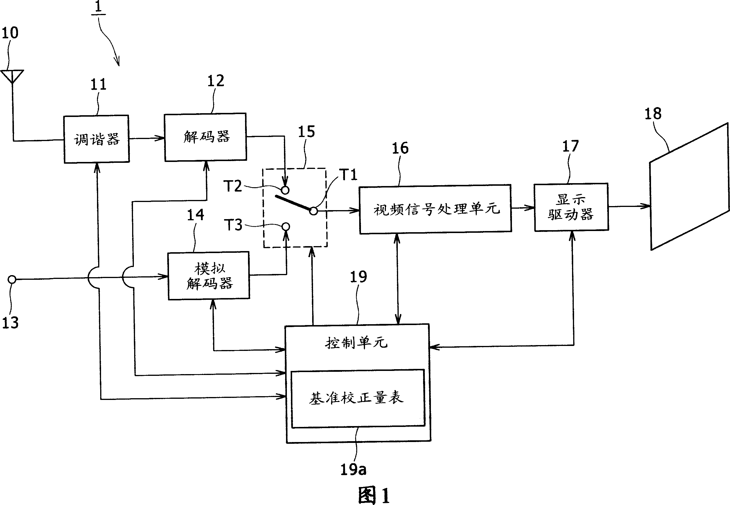
[0026] FIG. 1 shows the structure of a television receiver to which a display image correction device and an image display device according to an embodiment of the present invention are applied.

[0027] A broadcast electric wave received by an antenna 10 in the television receiver 1 shown in FIG. 1 is input to a tuner 11 . The tuner 11 performs carrier demodulation and the like on received radio waves input thereto. Then, under the control of the control unit 19 , the tuner 11 extracts and obtains a video signal of a specified channel, and outputs the video signal to the decoder 12 . For example, when a video signal input to the decoder 12 is scrambled, the decoder 12 performs demodulation processing to decode the video signal. In the present embodiment, since the video signal processing unit 16 in the subsequent stage is used to perform video signal processing by digital signal processing, a digital video signal is output from the decoder 12 .

[0028] In this case, the vi...


PUM


Abstract

Disclosed herein is a display image correcting device including, retaining means configured to retain reference correction amount data for correcting nonuniformity as a predetermined factor of an image displayed on a basis of a video signal, the reference correction amount data representing an amount of correction at a predetermined horizontal and vertical position of the image, the amount of correction being obtained in correspondence with a video signal level as a reference, and correcting means configured to perform correction processing on the video signal in correspondence with a horizontal direction and a vertical direction of the image, and a brightness direction, and performing the correction processing on a basis of three-dimensional correction amount data obtained by making two-dimensional correction amount data corresponding to a horizontal and vertical position, the two-dimensional correction amount data being obtained on a basis of the reference correction amount data, linearly proportional or nonlinearly proportional to level of the video signal to be corrected.

Description

[0001] Cross References to Related Applications [0002] The present invention includes subject matter related to Japanese Patent Application No. 2005-283985 filed in Japan Patent Office on September 29, 2005 and Japanese Patent Application No. 2006-196669 filed in Japan Patent Office on July 19, 2006, which The entire contents are hereby incorporated by reference. technical field [0003] The present invention relates to a display image correction apparatus and method for performing correction processing on a video signal to correct a predetermined deterioration factor of a display image. The present invention also relates to an image display device to which such a configuration of a display image correction device or a method thereof is applied. Background technique [0004] For image display devices such as those that display images based on video signals, a phenomenon known as luminance non-uniformity may occur in which images appear uneven on the screen due to structur...

Claims


Application Information

Patent Timeline
Patent Type & Authority Applications(China)
IPC IPC(8): H04N5/57G09G5/00G09G3/34G09G3/36
Inventor 山形裕城地义树渕上俊成白浜旭
Owner SONY CORP
Why Eureka
Try Eureka