

Illumination device for refrigerator
a refrigerator and refrigerator technology, applied in the field of refrigerators, can solve the problems of insufficient inefficient illumination of storage space, and limitation of halogen lamps b>12/b>, and achieve the effects of reducing refrigeration efficiency and storage capacity, efficient illumination, and minimizing damage to refrigerators
- Summary
- Abstract
- Description
- Claims
- Application Information
AI Technical Summary
Benefits of technology
Problems solved by technology
Method used
Image

Examples
second embodiment
[0070] Next, an illumination device for a refrigerator according to the present invention will be described in more detail with reference to the accompanying drawings.
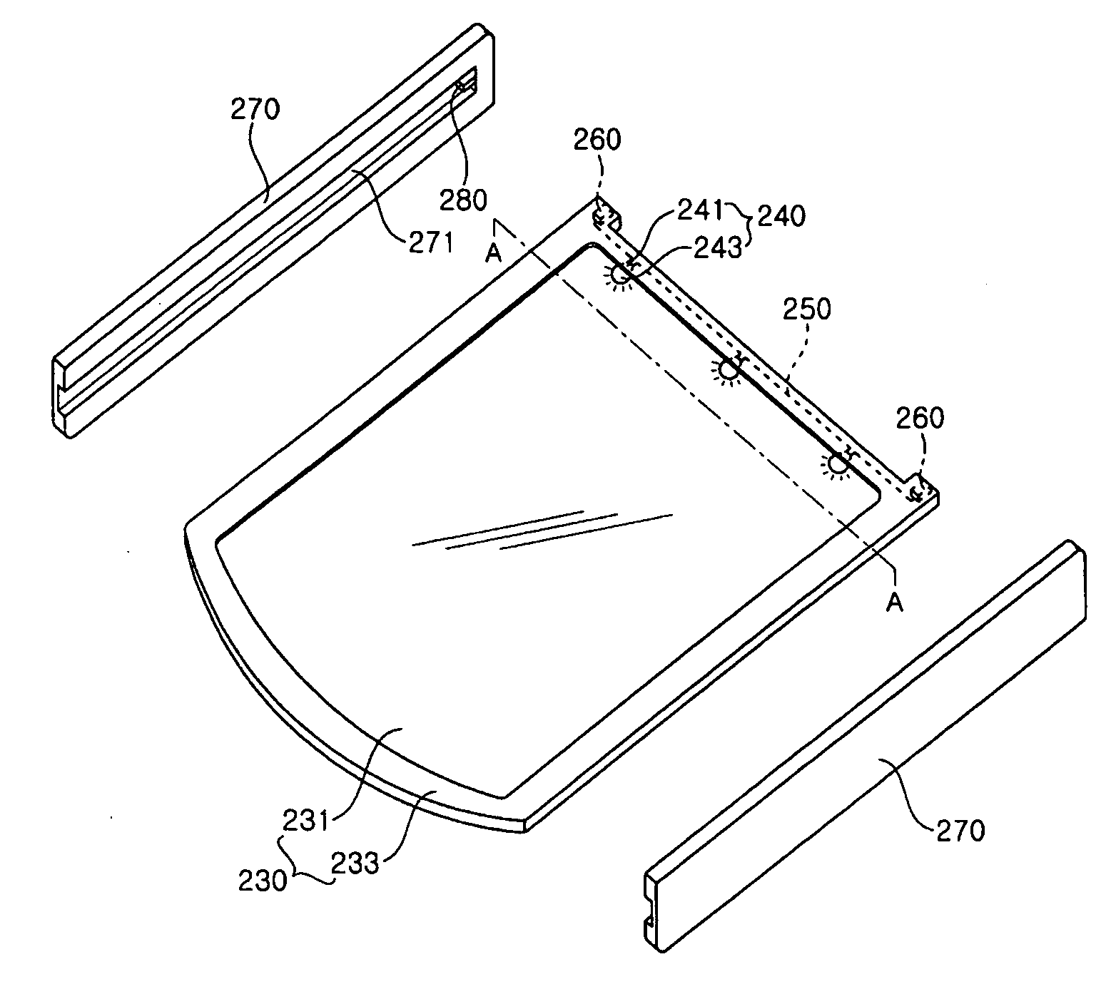
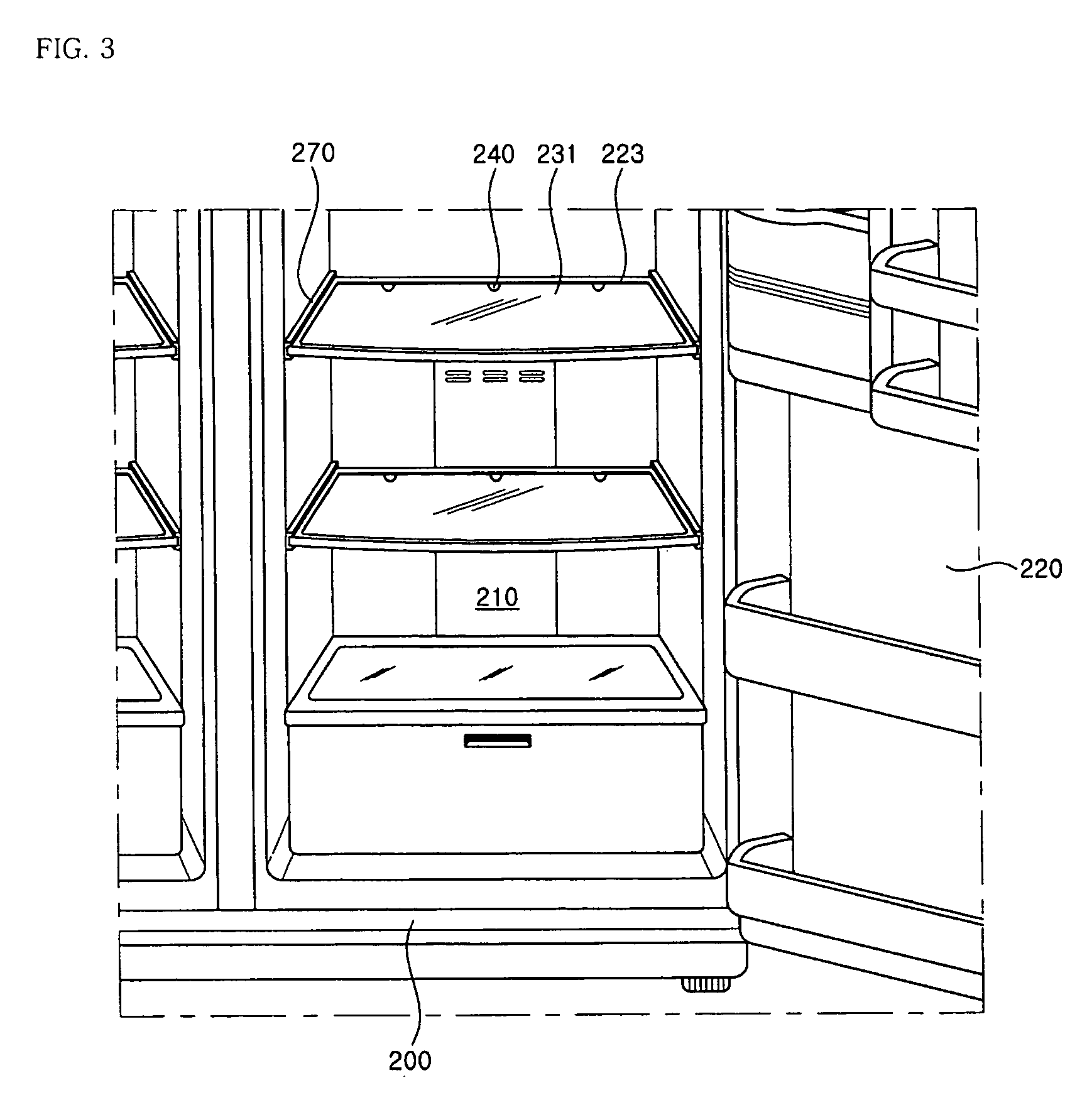
[0071]FIG. 3 is a front view showing the interior of a refrigerator provided with an illumination device for a refrigerator according to a second embodiment of the present invention, FIG. 4 is an exploded perspective view showing a shelf provided with the illumination device according to the second embodiment of the present invention and a support bracket for supporting the shelf, and FIG. 5 is a sectional view showing the shelf provided with the illumination device according to the second embodiment of the present invention.
[0072] As shown in the figures, a storage space 210 for storing foods therein is provided within a main body 200 of a refrigerator. The main body 210 is provided with a door 220 for selectively opening or closing the storage space 210, which can be pivoted in a forward and rearward direction.
[007...
third embodiment
[0087]FIG. 6 is a sectional view showing the interior of a refrigerator provided with an illumination device of a refrigerator according to the present invention.
[0088] As shown in the figure, a predetermined storage space 310 is defined within a main body 310 of a refrigerator. An illumination device for illuminating the storage space 310 is provided at one side of 310. The illumination device includes an illuminating source and an illuminating cover 330.
[0089] The illuminating source serves to emit light and substantially illuminate the storage space 310. The illuminating source includes a heat radiation plate 320 provided with a printed circuit board 321 at a front surface thereof, a light emitting diode module installed to the printed circuit board 321 of the heat radiation plate 320, and a molding portion 329 molded on the surface of the heat radiation plate 320 formed with the printed circuit board 321.
[0090] The heat radiation plate 320 is formed of metal and extends in a l...
fourth embodiment
[0112] In the present invention shown in FIG. 8, through-holes 425 and 427 are formed in the stepped portions 424 and 426 provided on lateral ends of a heat radiation plate 420 constituting an illuminating source, respectively. Coupling bosses 433 and 435 are provided at lateral ends on an inner surface of a front side of an illuminating cover 430 corresponding to the through-holes 425 and 427 of the stepped portions 424 and 426, respectively. Then, as a screw S3 that penetrated the through-hole 425 or 427 of the stepped portion 424 or 426 is fastened to a through-hole 434 or 436, the illuminating source is fixed to the illuminating cover 430.
[0113] The configuration for fixing the illuminating cover 430 into a storage space 410 is the same as that of the third embodiment of the present invention shown in FIG. 6. That is, a coupling bracket 437 and a coupling piece 439 are provided at rear ends of both lateral sides of the illuminating cover 430, respectively, and the coupling brack...
PUM
 Abstract
Description
Claims
Application Information