Switched reluctance motor speed regulating device, switched reluctance motor, and speed regulating device

A technology of switched reluctance motor and speed control device, which is applied in the direction of single motor speed/torque control, motor control, AC motor control, etc. The distance is uneconomical and other problems, and the effect of simple wiring, high reliability and improved driving power is achieved.

Active Publication Date: 2015-07-15
NIDEC BEIJING DRIVE TECH CO LTD
View PDF6 Cites 3 Cited by
  • Summary
  • Abstract
  • Description
  • Claims
  • Application Information

AI Technical Summary

Problems solved by technology

This way of using multiple power units to drive separately needs to solve the problem of drive consistency, and the reliability is not high; in addition, using the above technical solution, the motor needs a special design, such changes make the wiring of the switched reluctance motor too much. Very uneconomical when the distance between the drive unit and the motor is long

Method used


Image

  • Switched reluctance motor speed regulating device, switched reluctance motor, and speed regulating device
  • Switched reluctance motor speed regulating device, switched reluctance motor, and speed regulating device
  • Switched reluctance motor speed regulating device, switched reluctance motor, and speed regulating device

Examples


Embodiment Construction

[0051] In order to make the purpose, technical solutions and advantages of the embodiments of the present invention clearer, the technical solutions in the embodiments of the present invention will be clearly and completely described below in conjunction with the drawings in the embodiments of the present invention. Obviously, the described embodiments It is a part of embodiments of the present invention, but not all embodiments. Based on the embodiments of the present invention, all other embodiments obtained by persons of ordinary skill in the art without creative efforts fall within the protection scope of the present invention.

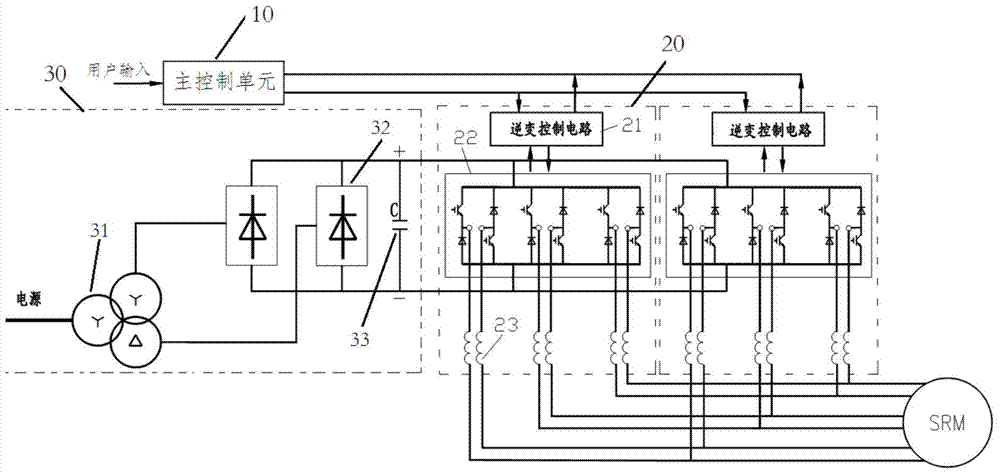
[0052] Such as image 3 As shown, the schematic circuit diagram of the switched reluctance motor speed regulating device provided by Embodiment 1 of the present invention. Such as image 3 As shown, the switched reluctance motor speed control device described in the first embodiment includes: a main control unit 10, a power supply unit 30, a pos...


PUM


Abstract

The invention relates to a switched reluctance motor speed regulating device, a switched reluctance motor, and a speed regulating method. The switched reluctance motor speed regulating device comprises a main control unit, a power supply unit used for providing working voltage, a position detection unit used for detecting the relative positions of a stator and a rotor of a switched reluctance motor and generating position detection information, and two or more power inverter units. The main control unit is used for generating a control instruction according to a speed regulating instruction which is input by a user and carries speed regulating parameters and the position detection information, and sends the control instruction to the two or more power inverter units. The two or more power inverter units are used for driving the switched reluctance motor according to the control instruction to enable the switched reluctance motor to run in a working state corresponding to the speed regulating parameters under the joint drive of the two or more power inverter units. High-power speed regulation can be realized without the need for special design of the motor.

Description

technical field [0001] The invention relates to the field of switched reluctance motors, in particular to a speed regulating device for a switched reluctance motor, a switched reluctance motor and a speed regulating method. Background technique [0002] The switched reluctance motor is a new type of speed control motor, which includes: a speed control device and a switched reluctance motor (Switched Reluctance Motor, referred to as SRM). Such as figure 1 As shown, the SRM is a double-salient pole variable reluctance motor, and the salient poles of the stator 1 and rotor 2 are laminated by ordinary silicon steel sheets. The rotor 2 has neither windings nor permanent magnets, and the salient poles of the stator 1 have concentrated windings 3, and the two radially opposite windings (such as figure 1 31 and 32 shown) are connected together and are called "one phase". There are many structural forms of switched reluctance motors, and the number of phases includes single-phase,...

Claims


Application Information

Patent Timeline
Patent Type & Authority Applications(China)
IPC IPC(8): H02P6/08H02P25/08H02P27/08
CPCH02P6/08H02P25/08H02P27/06H02P2203/03
Inventor 丁金龙
Owner NIDEC BEIJING DRIVE TECH CO LTD
Why Eureka
Try Eureka