
Displacement sensor

A technology of displacement sensor and amplifying unit, applied in the field of displacement sensor, can solve the problems of inability to detect displacement, inability to use displacement sensor, complicated circuit structure, etc.

Active Publication Date: 2015-07-22
SHINKO ELECTRIC CO LTD +1
View PDF10 Cites 4 Cited by
  • Summary
  • Abstract
  • Description
  • Claims
  • Application Information

AI Technical Summary

Problems solved by technology

[0004] In the above-mentioned displacement sensor, it is necessary to supply the AC current from the oscillator to the coil, so it is necessary to provide an oscillator in addition to the coil, and the circuit configuration becomes complicated.
Moreover, a switch and a switching control circuit for switching between AC current and DC current are required, and the circuit structure becomes more complicated, so it is not suitable to install the displacement sensor in a place where the installation space is small.
In addition, since temperature compensation is performed by supplying a DC current to the coil every predetermined sampling period, displacement detection cannot be performed during this temperature compensation period.
For example, when detecting the displacement of a valve of an internal combustion engine, it is necessary to continuously detect the displacement, and the displacement sensor of Patent Document 1 cannot be used.

Method used


Image

  • Displacement sensor
  • Displacement sensor
  • Displacement sensor

Examples


Embodiment Construction

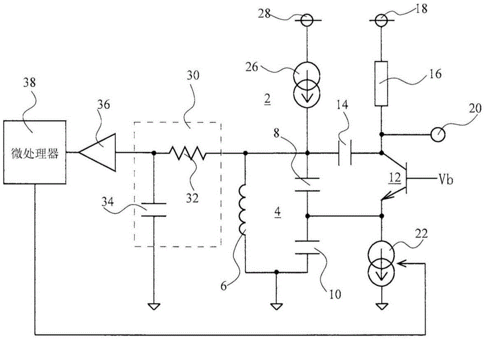
[0015] The displacement sensor of one embodiment of the present invention is, for example, an eddy current displacement sensor, such as figure 1 As shown, there is a self-oscillating oscillator, for example a Colpitts oscillator circuit 2 . The Colpitts oscillator circuit 2 has a parallel resonant unit, for example, a parallel resonant circuit 4 . This parallel resonant circuit 4 is formed by connecting a series circuit of two capacitors 8 and 10 to the coil 6 in parallel. For the parallel resonance circuit 4 , the values ​​of the coil 6 and the capacitors 8 and 10 are selected so that the parallel resonance circuit 4 resonates in parallel at a predetermined frequency. Furthermore, the Colpitts oscillating circuit 2 further has an active element such as a bipolar transistor, specifically an NPN transistor 12 . The NPN transistor 12 has: a first electrode such as a base; a second electrode such as an emitter; and a third electrode such as a collector. An appropriate bias vol...


PUM


Abstract

Provided is a displacement sensor. A parallel resonant circuit (4) comprising a coil (6) and capacitors (8, 10) is disposed on an output side of an NPN transistor (12), an output of the parallel resonant circuit (4) is fed back to an input side of the transistor (12), and then a continuously oscillating Colpitts oscillating circuit (2) is formed. An output level of the transistor (12) is changed according to a change of a position of a measured object relative to the coil (6). A constant current source (26) continuously provides a direct current for the coil (6). An RC low-pass filter (30) detects a change of a direct current resistance value of the coil (6) according to voltage reduction caused by a direct current flowing through the coil (6). A microprocessor (38) adjusts the output level of the transistor (12) on the basis of an output of the RC low-pass filter (30).

Description

technical field [0001] The invention relates to a displacement sensor which uses a coil to detect the position change of the object to be measured, in particular to compensating the error caused by the change of the resistance value of the coil with temperature. Background technique [0002] As a displacement sensor using a coil, for example, there is an eddy current type displacement sensor. The eddy current displacement sensor utilizes the following principle: When a conductor as an object to be measured approaches a coil through which an alternating current flows, an eddy current flows through the conductor to generate an alternating magnetic field, thereby changing the impedance of the coil. In this eddy current displacement sensor, the impedance of the coil also changes according to the temperature change of the use environment, so it is necessary to compensate for the impedance change caused by the temperature change. An example of this compensation technique is discl...

Claims


Application Information

Patent Timeline
Patent Type & Authority Applications(China)
IPC IPC(8): G01B7/02
CPCG01R33/0005G01R33/0082
Inventor 中野泰志井上直也东城孝一加藤英雄久保山丰
Owner SHINKO ELECTRIC CO LTD
Learn More