Coil and fabrication device therefor, and coil fabrication method

A technology for manufacturing devices and coils, applied in the field of coils and manufacturing devices thereof

Active Publication Date: 2015-07-22
TOSHIBA IND PROD & SERVICES CORP
View PDF7 Cites 0 Cited by
  • Summary
  • Abstract
  • Description
  • Claims
  • Application Information

AI Technical Summary

Problems solved by technology

At this time, in order to correct the deviation, it is necessary to temporarily stop the winding and perform so-called meandering adjustment on the unwinding side (material supply side), which becomes a burden of work.

Method used


Image

  • Coil and fabrication device therefor, and coil fabrication method
  • Coil and fabrication device therefor, and coil fabrication method
  • Coil and fabrication device therefor, and coil fabrication method

Examples


no. 1 Embodiment approach

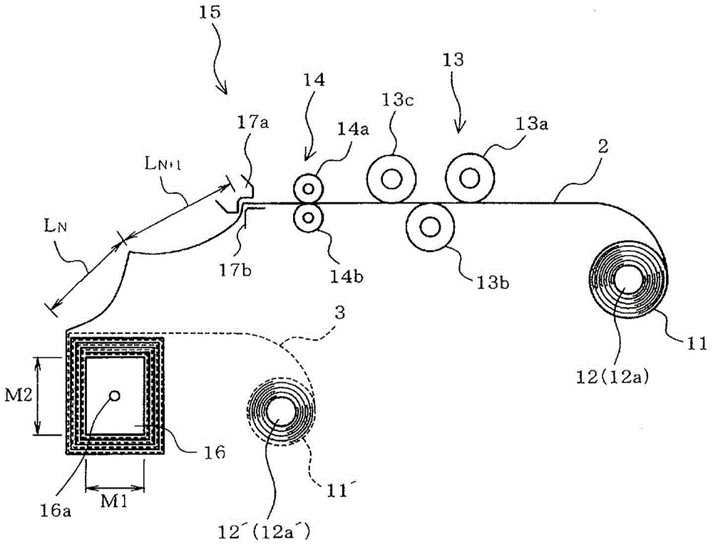
[0019] Below, refer to Figure 1 to Figure 4 A first embodiment applied to a coil used in a transformer will be described.

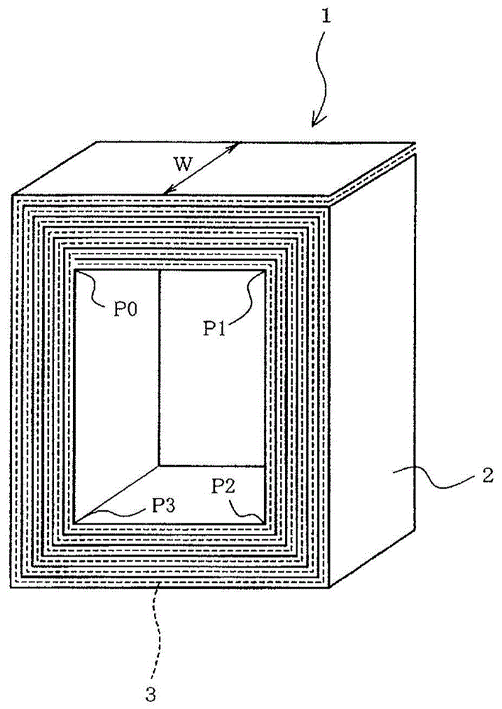
[0020] Such as image 3 As shown, the manufactured coil 1 is formed by forming a strip-shaped metal sheet 2 and a strip-shaped insulating sheet 3 relative to the coil frame (refer to figure 1 The reference number 16) is wound and constituted in multiple layers, and is formed, for example, in a square tube shape as a whole. The metal sheet 2 is, for example, a metal thin plate material made of aluminum, and the insulating sheet 3 is, for example, insulating paper. Coil 1 is formed as the image 3 The metal sheet 2 denoted by the reference symbol W does not deviate in the width direction, and no gap occurs between the layers wound in multiple layers. In addition, the metal sheet 2 may also be formed of other metal materials such as copper.

[0021] exist figure 1 In the manufacturing device of the coil 1 shown, the reference numeral 11 is a winding b...

no. 2 Embodiment approach

[0051] Figure 5 The second embodiment is shown, and the same reference numerals and the like are attached to the same parts as those already described to omit description, and the different points will be described below.

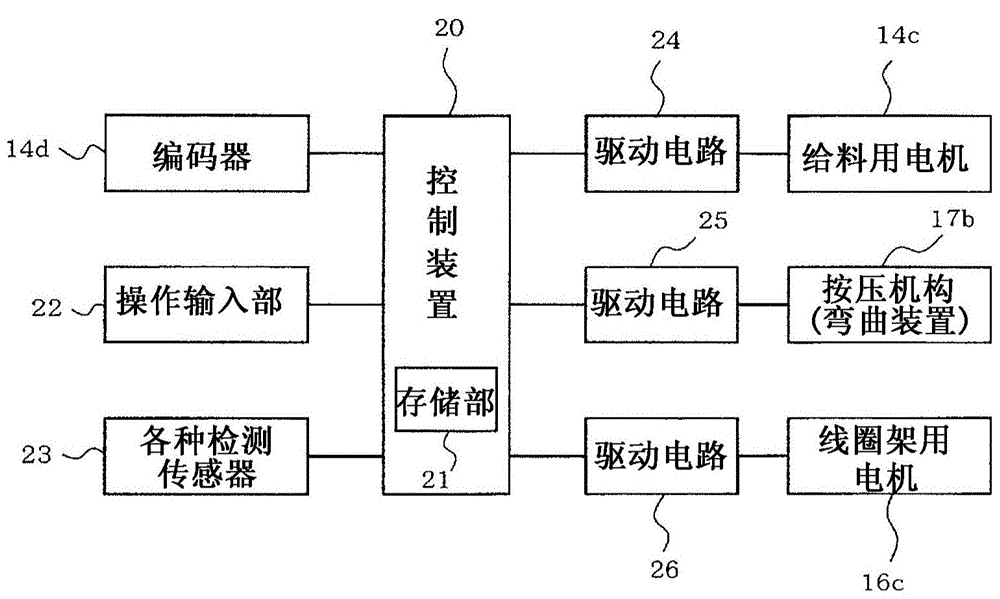
[0052] The bobbin 30 of the second embodiment has a cylindrical shape in which the outer peripheral shape is annular when viewed from the axial direction of the rotating shaft 16a. The bending device 31 as a bending unit is composed of, for example, a plurality of forming rollers 31 a to 31 c, and is configured to form bending marks corresponding to the curvature of the bobbin 30 or the curvature of the metal sheet 2 wound on the bobbin 30 .

[0053] Specifically, in the storage unit 21 , data on the feeding amount of the metal piece 2 and the radius of curvature corresponding to each type of the bobbin 30 are stored in advance as coil information. In addition, the control device 20 changes the feeding amount in conjunction with the data on the radius of ...


PUM


Abstract

A coil fabrication device according to the present embodiment comprises: a bending means for carrying out a bending work upon a metal sheet which is sent from a feeder, prior to rolling upon a former; and a control means for, with respect to the metal sheet, controlling the bending work of the bending means on the basis of the degree of sending the metal sheet from the feeder, such that the shape of the initial roll upon the former conforms to the outer circumference shape of the former, and thereafter, that the shape conforms to the outer circumference shape of the metal sheet which is rolled in overlapping layers upon said former.

Description

technical field [0001] Embodiments of the present invention relate to a coil, a manufacturing device thereof, and a coil manufacturing method. Background technique [0002] Conventionally, in electric power and industrial static induction equipment, such as coils of transformers, there has been provided a structure in which a strip-shaped metal sheet serving as a conductor is wound around a coil former. For this type of coil, square or cylindrical bobbins are used according to its specifications. In addition, the metal sheet is wound in multiple layers with respect to the bobbin together with, for example, an insulating sheet made of an insulating material, and a cooling duct is arranged in an arbitrary layer of the layers. [0003] It is preferable to improve the dimensional accuracy by winding the coil such that the metal piece is in close contact with the bobbin. However, due to the rigidity of the metal sheet, even if the winding torque of the bobbin is increased, gaps...

Claims


Application Information

Patent Timeline
IPC IPC(8): H01F41/04H01F27/28H01F41/06
CPCH01F41/065H01F41/0691H01F41/0683H01F41/0604H01F27/2847H01F41/061H01F41/063H01F41/071H01F41/077H01F41/096H01F41/04
Inventor 逵村祐介
Owner TOSHIBA IND PROD & SERVICES CORP
Why Eureka
Try Eureka