Component Mounting Machine

A technology for installing machines and components, applied in the direction of electrical components, electrical components, etc., can solve the problems of narrow focus height range and inability to shoot clearly at the same time, and achieve the effect of improving judgment accuracy and position accuracy

Active Publication Date: 2018-09-28
FUJI KK
View PDF3 Cites 0 Cited by
  • Summary
  • Abstract
  • Description
  • Claims
  • Application Information

AI Technical Summary

Problems solved by technology

As a result, the range of appropriate focus heights becomes narrow, and it may not be possible to clearly image nozzles and position reference marks at different heights at the same time.

Method used


Image

  • Component Mounting Machine
  • Component Mounting Machine
  • Component Mounting Machine

Examples


Embodiment Construction

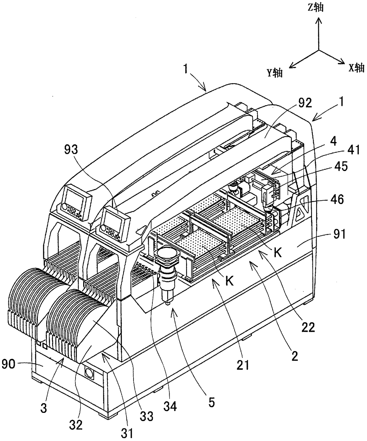
[0035] refer to Figure 1 ~ Figure 3 The component mounting machine 1 according to the first embodiment of the present invention will be described. figure 1 It is a perspective view which shows the whole structure of the component mounting machine 1 of 1st Embodiment. figure 1 It is shown that two component mounting machines 1 are arranged side by side on the common base 90 , and one will be described later. The component mounting machine 1 is configured by assembling a substrate conveying device 2, a component supply device 3, a component transfer device 4, an imaging device 5, and a control computer not shown in the figure on a machine table 91 (the reference numerals are only assigned to the components on the right front side). Installer 1). Such as figure 1 As shown by the XYZ coordinate axes on the upper right, the horizontal width direction of the component mounting machine 1 ( figure 1 The direction from the upper left to the lower right of the paper surface) is set...


PUM


Abstract

There is provided a component mounting machine, including: a component supply device which supplies plural types of components; a component transfer device which includes a mounting head having a suction nozzle for sucking the components from the component supply device and mounting the components on a positioned substrate, and a head driving mechanism which moves the mounting head in a horizontal plane; and an imaging device which includes an image sensor and a main lens, and images an image in a state where the suction nozzle sucks the component from below. The imaging device includes a plurality of sub-lenses that are disposed between the mounting head and the image sensor, and takes an image of position fiducial marks that are respectively disposed in plural types of mounting heads by the image sensor through any of the sub-lens and the main lens. Accordingly, it is possible to image the position fiducial mark in which at least one of an installation position and a disposition height is different in plural types of mounting heads, and the component which is sucked by the suction nozzle at the same time, and to contribute to improving the accuracy of a component mounting by obtaining a clear image. Furthermore, it is possible to perform on-the-fly imaging, and to shorten mounting tact time.

Description

technical field [0001] The present invention relates to a component mounting machine for mounting components on a board, and more specifically, to an imaging device equipped in the component mounting machine. Background technique [0002] There are solder printing machines, component mounting machines, board inspection machines, reflow soldering machines, etc. as equipment for producing boards on which many components are mounted, and they are usually connected by a board transfer device to form a board production line. Among them, the component mounting machine includes a substrate conveying device, a component supply device, a component transfer device, and an imaging device, and shares the work of mounting components on the substrate. The imaging device captures the image of the state of the suction nozzle of the component transfer device from below to confirm the state of the component suction. [0003] Here, in order to accurately grasp the position of the moving sucti...

Claims


Application Information

Patent Timeline
Patent Type & Authority Patents(China)
IPC IPC(8): H05K13/08H05K13/04
CPCH05K13/0812
Inventor 山荫勇介井土武洋吉野朋治
Owner FUJI KK
Why Eureka
Try Eureka