LED display control method and LED lamp plate

A display control method and LED array technology, applied to static indicators, instruments, etc., can solve the problem of darkening in the first scan and achieve the effect of reducing parasitic charges

Inactive Publication Date: 2015-08-05
XIAN NOVASTAR TECH
View PDF4 Cites 5 Cited by
  • Summary
  • Abstract
  • Description
  • Claims
  • Application Information

AI Technical Summary

Problems solved by technology

[0006] In order to overcome the defects in the prior art, the present invention provides an LED display control method and an LED lamp panel to solve the problem of the first scan dimming in the prior art

Method used


Image

  • LED display control method and LED lamp plate
  • LED display control method and LED lamp plate
  • LED display control method and LED lamp plate

Examples


Embodiment Construction

[0024] In order to make the above objects, features and advantages of the present invention more comprehensible, specific implementations of the present invention will be described in detail below in conjunction with the accompanying drawings.

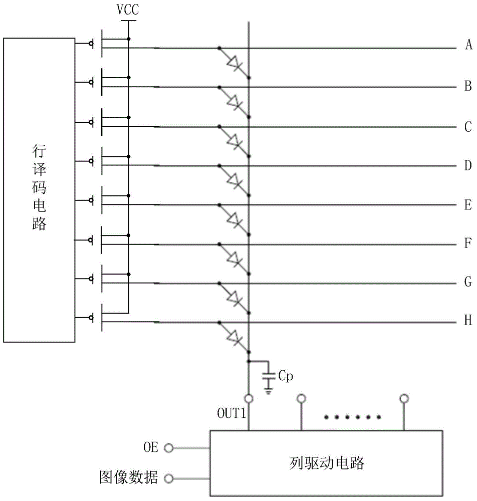
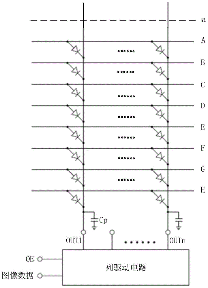
[0025] See image 3 , which is a circuit diagram related to LED lamp panel scanning provided by an embodiment of the present invention. Specifically, as image 3 As shown, the LED light board (or LED display unit board) includes: multiple scanning lines (or row lines) A~H, multiple data lines (or column lines), LED arrays and column drive circuits, and of course Including row decoding circuit (will be combined later Figure 4 with Figure 5 be detailed); in addition, in image 3 In the embodiment of the present invention, the scanning line a may be a real scanning line that is not connected to an LED, or may be a virtual scanning line, so it is represented by a dotted line.

[0026] The LED array is in image 3 It is an 8*n LED a...


PUM


Abstract

The invention relates to an LED display control method and an LED lamp plate. The LED display control method is suitable for driving an LED array which is electrically connected with M scan lines and N data lines. The M scan lines are electrically connected with a row decoding circuit. The N data lines are electrically connected with a column driving circuit, wherein M and N are positive integers which are larger than one. The LED display control method comprises the steps of receiving image data through the column driving circuit for driving the N data lines and outputting a line selection signal through the row decoding circuit for successively driving the M scan lines to perform M times of scanning; and performing one time of idle scanning before successively driving the M scan lines for performing M times of scanning, wherein in the idle scanning, the image data are output through the column driving circuit so that at least one data line in the N data lines is conducted with the column driving circuit and the row decoding circuit does not supply a row selection signal for the LED. Therefore the LED display control method and the LED lamp plate can settle a problem of relatively low brightness in first scanning according to the prior art.

Description

technical field [0001] The invention belongs to the technical field of LED display control, and in particular relates to an LED display control method and an LED lamp board. Background technique [0002] Since 2012, the pitch of LED display screens has broken through below P3, but in the process of use, the dimming of the first scan has always been a bottleneck for high-density small-pitch LED displays. [0003] At present, when the LED scanning display control system drives the LED screen with a general-purpose on-off driver chip or a PWM driver chip, the grayscale is realized through subfields, and each subfield sends a certain 1bit (bit) of grayscale data, and then through Control the turn-on time of the driver chip to realize the weight corresponding to the bit. Usually, in order to improve the refresh rate of the scanning display screen, it is not to achieve the gray level of a certain line before realizing the gray level of the next line, but to divide the total numbe...

Claims


Application Information

Patent Timeline
Patent Type & Authority Applications(China)
IPC IPC(8): G09G3/32
Inventor 梁伟周晶晶刘德福
Owner XIAN NOVASTAR TECH
Why Eureka
Try Eureka