A kind of LED display device and display method thereof
A LED display and display panel technology, applied to static indicators, instruments, etc., can solve the problems of not being able to further increase the operating speed and reduce storage space, and achieve the effect of avoiding data repetition and reducing storage space
- Summary
- Abstract
- Description
- Claims
- Application Information
AI Technical Summary
Problems solved by technology
Method used
Image
Examples
Embodiment 1
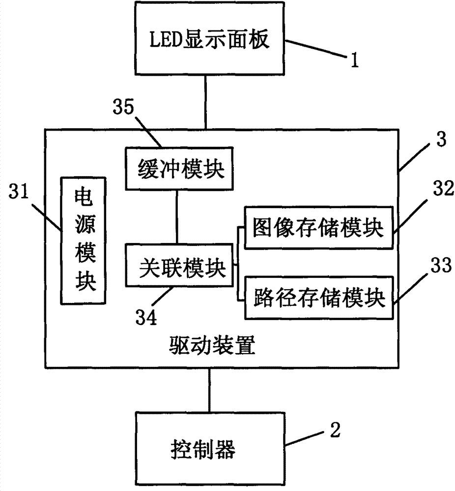
[0020] refer to figure 1 , a kind of LED display device, comprises LED display panel 1 and controller 2, is provided with driving device 3 between LED display panel 1 and controller 2, and driving device 3 comprises power supply module 31, image storage module 32, path storage Module 33, association module 34 and buffer module 35, image storage module 32 and path storage module 33 are respectively connected to association module 34, association module 34 is connected to LED display panel 1 through buffer module 35, mains power supply to LED through power supply module 31 The display panel 1 supplies power, and the controller 2 is respectively connected to the image storage module 32 , the path storage module 33 and the association module 34 . Wherein, the controller 2 adopts the S7-200 series PLC of Siemens Company, of course, it can also be realized by other methods similar to single-chip microcomputer or industrial PC, which will not be described in detail here. The power s...
Embodiment 2
[0031] The hardware structure of this embodiment is the same as that of Embodiment 1, and will not be described in detail here.
[0032] The method for displaying using the device includes the following steps:
[0033] A. Store the image to be displayed into the image storage module 32 through the controller 2, and store the image display path into the path storage module 33;
[0034] B. The association module 34 retrieves the corresponding image from the image storage module 32 according to the display command input by the controller 2, and retrieves the corresponding image display path from the path storage module 33, and associates the image with the image display path through the buffer Module 35 output;
[0035] C, the association module 34 carries out the degree of association sorting of the paths associated with the different images displayed at the same time, establishes the mapping relationship of the path coordinates, and records it in the buffer module 35, and the ...
Embodiment 3
[0041] The hardware structure of this embodiment is the same as that of Embodiment 1, and will not be described in detail here.
[0042] The method for displaying using the device includes the following steps:
[0043] A. Store the image to be displayed into the image storage module 32 through the controller 2, and store the image display path into the path storage module 33;
[0044] B. The association module 34 retrieves the corresponding image from the image storage module 32 according to the display command input by the controller 2, and retrieves the corresponding image display path from the path storage module 33, and associates the image with the image display path through the buffer Module 35 output;
[0045] C, the association module 34 carries out the degree of association sorting of the paths associated with the different images displayed at the same time, establishes the mapping relationship of the path coordinates, and records them in the buffer module 35, and the ...
PUM
 Abstract
Description
Claims
Application Information
 - R&D
- Intellectual Property
- Life Sciences
- Materials
- Tech Scout
- Unparalleled Data Quality
- Higher Quality Content
- 60% Fewer Hallucinations
Browse by: Latest US Patents, China's latest patents, Technical Efficacy Thesaurus, Application Domain, Technology Topic, Popular Technical Reports.
© 2025 PatSnap. All rights reserved.Legal|Privacy policy|Modern Slavery Act Transparency Statement|Sitemap|About US| Contact US: help@patsnap.com


