Seat and electromechanical stretching device

A stretching device and mechanical technology, applied in the direction of chairs, reclining chairs, home appliances, etc., can solve the problems of reducing comfort, bulky, and moving clothes on the back, reducing weight and cost, optimizing motion mechanisms, and improving comfort. Effect

Active Publication Date: 2017-12-26
UE FURNITURE CO LTD
View PDF6 Cites 0 Cited by
  • Summary
  • Abstract
  • Description
  • Claims
  • Application Information

AI Technical Summary

Problems solved by technology

[0003] Specifically, traditionally, the electromechanical stretching device generally includes a fixed base, a stretching assembly and a driving assembly arranged on the fixing base. The driving assembly is used to drive the expansion and reset of the stretching assembly. And the left and right leg rest assembly, cushion support assembly and backrest assembly are arranged in pairs, the front and rear ends of the cushion support assembly are respectively hinged with one end of the leg rest assembly and the backrest assembly, and the cushion support assembly generally includes a support connector A, a support Connector B and support connector C, the cushion support assembly generally consists of a fixed seat, support connector A, support connector B and support connector C to form a four-bar linkage mechanism, the movement of the cushion support component will drive the backrest hingedly connected to it component movement, but in the prior art, the movement mode of the cushion support component and the backrest component will cause the user’s back clothing to move up, which reduces the comfort; at the same time, the current electromechanical stretching device has a complicated structure, a large volume and is very heavy, resulting in Waste of space, inconvenient transportation, etc.

Method used


Image

  • Seat and electromechanical stretching device
  • Seat and electromechanical stretching device
  • Seat and electromechanical stretching device

Examples


Embodiment 1

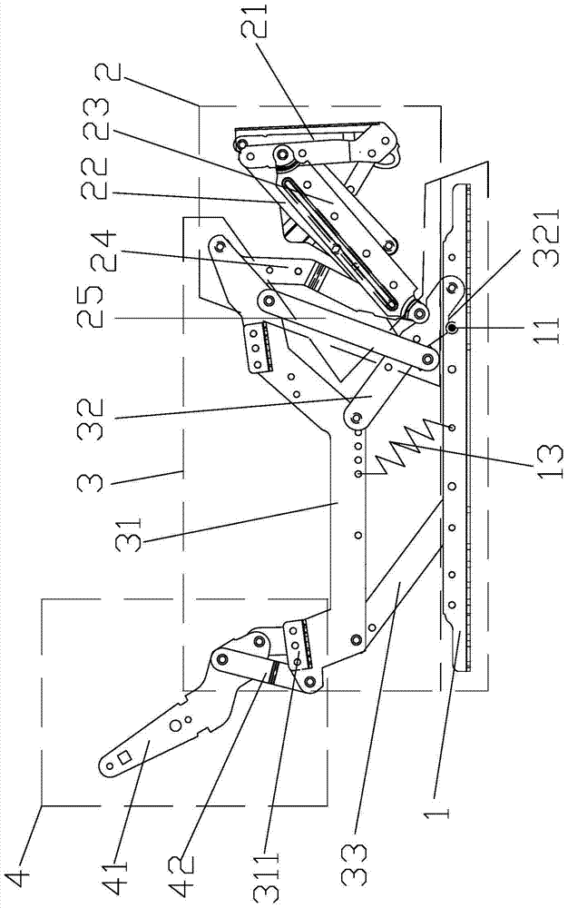
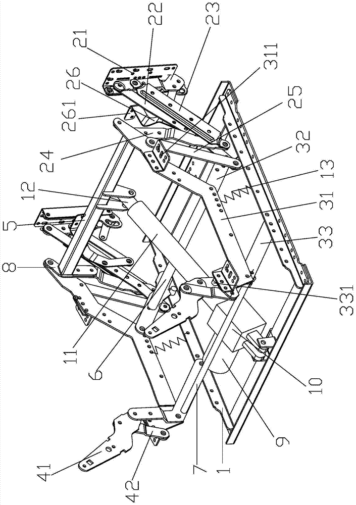
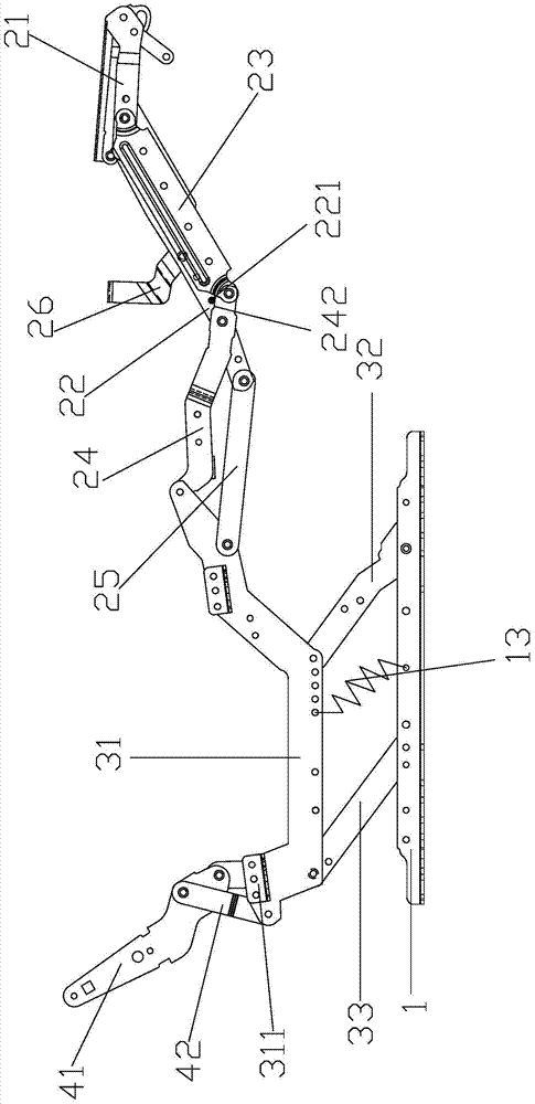
[0035] Such as Figure 1-6As shown, a seat and its electromechanical stretching device, the electromechanical stretching device includes a fixed seat 1 and an extension assembly and a drive assembly arranged on the fixation seat 1, the drive assembly is used to drive the extension and reset of the extension assembly, and the extension assembly It includes leg rest assembly 2, seat cushion support assembly 3 and backrest assembly 4 located on the left and right sides of the fixed seat 1 and arranged in pairs. One end is hinged; specifically, the cushion support assembly 3 includes a support connector A31, a support connector B32 and a support connector C33, and forms a four-bar linkage together with the fixed base 1, and one end of the support connector A31 is connected to the legrest The board assembly 2 is hinged, and the backrest assembly 4 includes a backrest connector A41 and a backrest connector B41; one end of the support connector B32 is hinged to the middle section of ...


PUM


Abstract

The invention discloses a seat and an electromechanical stretching device. The seat cushion support assembly includes a support connector A, a support connector B, and a support connector C. One end of the support connector A is hinged to a leg rest assembly. The backrest assembly includes a backrest Connecting piece A and backrest connecting piece B; one end of supporting connecting piece B is hinged with the middle section of supporting connecting piece A, the other end of supporting connecting piece B is hinged with the fixing seat, and the middle end of supporting connecting piece C is connected with the middle section of supporting connecting piece A Hinged and one end of the support connector C is hinged with the fixed seat, the other end of the support connector C is hinged with one end of the backrest connector A, the other end of the support connector A is hinged with one end of the backrest connector B, and the backrest connector B is hinged. The other end is hinged with the middle section of the backrest connector A; a drive assembly drives the device to move. The technical solution optimizes the motion mechanism, improves comfort, saves materials, and has low cost.

Description

technical field [0001] The invention belongs to the field of furniture, and relates to a seat such as a lounge chair, a sofa, etc., and in particular to an electromechanical stretching device used therein. Background technique [0002] At present, many furniture such as lounge chairs and sofas are equipped with electromechanical extension devices, on which backrests, seat cushions and leg rests are installed, and electromechanical extension devices are usually a combination of various mechanical connectors. The components are operable to provide various comfort features, such as independent reclining movement of the seat assembly, and actuation of the extendable leg rest assembly and associated tilting of the chair frame. While many conventional recliners operate satisfactorily, furniture manufacturers are continually pursuing improved chair frames and functional frames that reduce system complexity, improve smooth operation, and occupant comfort. [0003] Specifically, tra...

Claims


Application Information

Patent Timeline
Patent Type & Authority Patents(China)
IPC IPC(8): A47C1/035
Inventor 李立波李文才
Owner UE FURNITURE CO LTD
Why Eureka
Try Eureka