Valve surface grinding device and grinding method thereof
A technology of a grinding device and a grinding method, which is applied to grinding driving devices, seat surface grinding machines, grinding machines, etc., can solve the problems of time-consuming, waste of manpower, and deep valve surface, and achieve the effect of simple grinding method and improving grinding efficiency.
- Summary
- Abstract
- Description
- Claims
- Application Information
AI Technical Summary
Problems solved by technology
Method used
Image
Examples
Embodiment 1
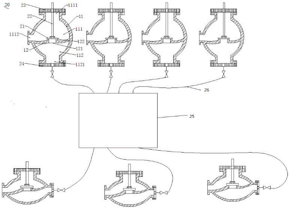
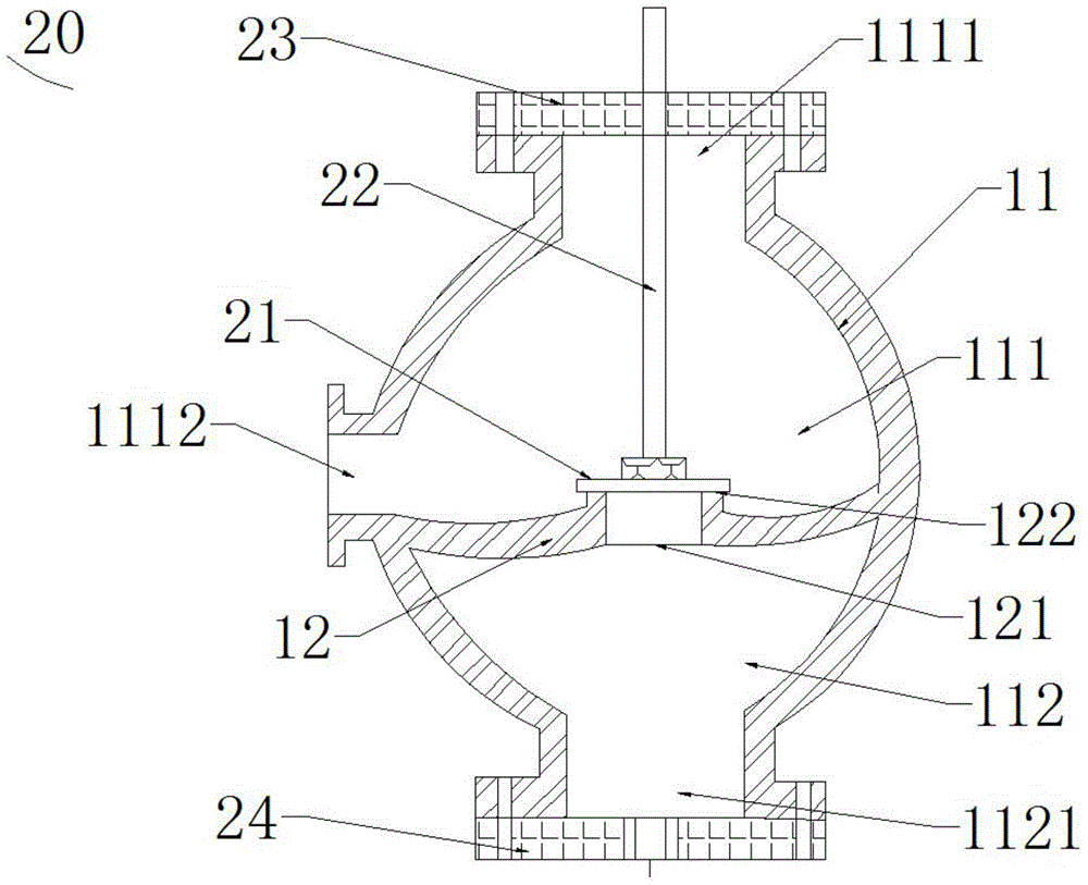
[0024] Please also see figure 2 with image 3 , figure 2 It is a schematic diagram of the overall structure of the grinding device 20 applied to the valve face in Embodiment 1 of the present invention; image 3 It is a partial structural schematic diagram of a grinding device 20 applied to a valve face in Embodiment 2 of the present invention. The grinding device 20 applied to the valve surface includes a mold 21 for grinding the valve surface, a guide rod 22 for driving the grinding tool 21 to make it reciprocate up and down along the center line of the valve seat opening, and a guide rod 22 for stabilizing the guide rod to make it A valve cover plate 23 that can move linearly up and down in the valve body, a sealing plate 24 for blocking the outlet, an air compression unit 25 for generating compressed air, and an air compression unit 25 for connecting the sealing plate 24 and the air compression unit 25 and compressing the gas Delivered to the gas delivery tube 26 in th...
Embodiment 2
[0033] see Figure 4 , which is the overall structure diagram of the grinding device applied to the valve face in Embodiment 2 of the present invention. On the basis of the structure of Embodiment 1, the grinding device applied to the valve face in this embodiment also includes a compressed air distribution air bag 27 . The air compression unit 25 is connected to the gas delivery pipe 26 through the compressed air distribution air bag 27, so that the compressed air from the air compression unit 25 can be buffered by the compressed air distribution air bag 27 and then flow to the outlet cavity 112. Inflate to reduce the damage of high-pressure compressed air to the outflow cavity 112 of the valve body 11 . The compressed air distribution air bag 27 is provided with a plurality of control valves 271 . Multiple shut-off valves to be ground can be connected to multiple control valves 271 of the compressed air distribution air bag 27 through their respective gas delivery pipes 26...
PUM
 Abstract
Description
Claims
Application Information
 - R&D
- Intellectual Property
- Life Sciences
- Materials
- Tech Scout
- Unparalleled Data Quality
- Higher Quality Content
- 60% Fewer Hallucinations
Browse by: Latest US Patents, China's latest patents, Technical Efficacy Thesaurus, Application Domain, Technology Topic, Popular Technical Reports.
© 2025 PatSnap. All rights reserved.Legal|Privacy policy|Modern Slavery Act Transparency Statement|Sitemap|About US| Contact US: help@patsnap.com


