
Grinding device and grinding method applied to valve face

A technology of grinding device and grinding method, which is applied in the direction of grinding drive device, seat surface grinding machine, grinding machine, etc., can solve the problems of time-consuming, low work efficiency, scratches, etc., and achieve the effect of improving grinding efficiency and simple grinding method

Active Publication Date: 2016-10-26
广州文冲船舶修造有限公司
View PDF3 Cites 1 Cited by
  • Summary
  • Abstract
  • Description
  • Claims
  • Application Information

AI Technical Summary

Problems solved by technology

However, in the process of fine sand grinding, if you do not pay attention to mixing one or two coarse sands, with the movement of the abrasive tool, it is easy to cause deep scratches on the valve surface, especially on the softer copper valve seat. Deeper
Once this happens, all previous efforts will be wasted, and it will be re-grinded from coarse sand grinding, which will seriously affect the grinding efficiency of the valve surface
Especially when it is necessary to overhaul the valve surface of the globe valve in large quantities, the method of manually sliding friction grinding the valve surface is not only time-consuming, but also a waste of manpower and low work efficiency

Method used


Image

  • Grinding device and grinding method applied to valve face
  • Grinding device and grinding method applied to valve face
  • Grinding device and grinding method applied to valve face

Examples


Embodiment 1

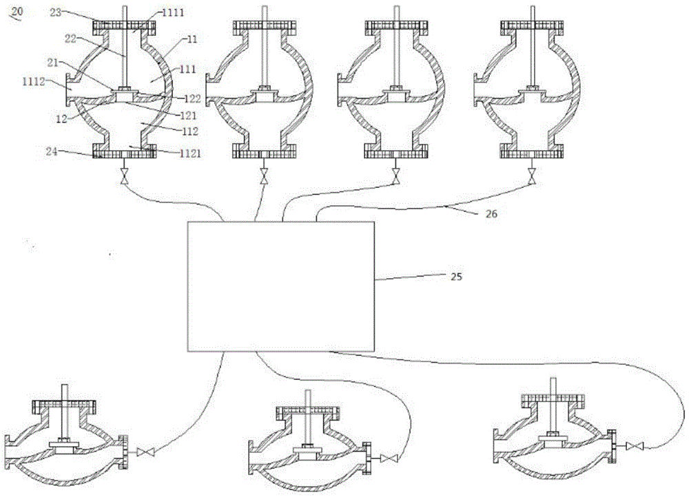
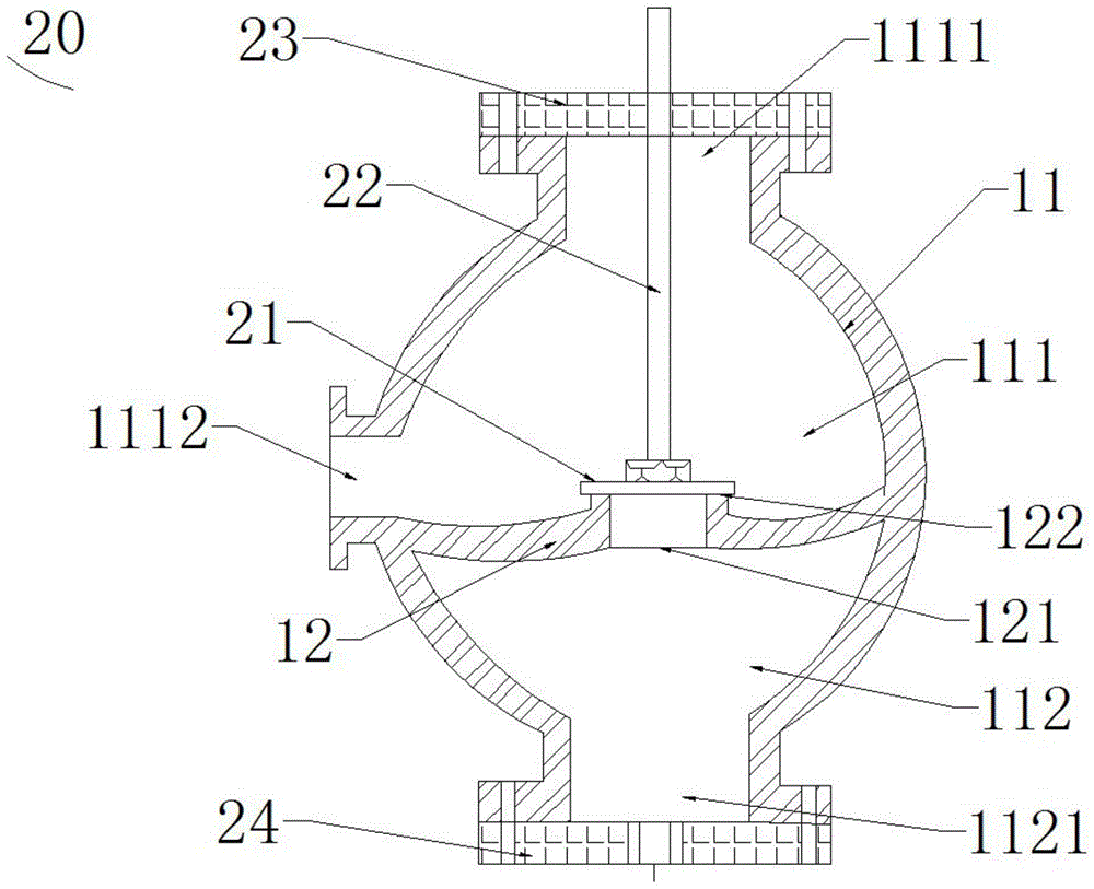
[0024] Please also see figure 2 and image 3 , figure 2 It is a schematic diagram of the overall structure of the grinding device 20 applied to the valve face in Embodiment 1 of the present invention; image 3 It is a partial structural schematic diagram of a grinding device 20 applied to a valve face in Embodiment 2 of the present invention. The grinding device 20 applied to the valve surface includes a mold 21 for grinding the valve surface, a guide rod 22 for driving the grinding tool 21 to make it reciprocate up and down along the center line of the valve seat opening, and a guide rod 22 for stabilizing the guide rod to make it A valve cover plate 23 that can move linearly up and down in the valve body, a sealing plate 24 for blocking the outlet, an air compression unit 25 for generating compressed air, and an air compression unit 25 for connecting the sealing plate 24 and the air compression unit 25 and compressing the gas Delivered to the gas delivery tube 26 in the...

Embodiment 2

[0033] see Figure 4 , which is the overall structure diagram of the grinding device applied to the valve face in Embodiment 2 of the present invention. On the basis of the structure of Embodiment 1, the grinding device applied to the valve face in this embodiment also includes a compressed air distribution air bag 27 . The air compression unit 25 is connected to the gas delivery pipe 26 through the compressed air distribution air bag 27, so that the compressed air from the air compression unit 25 can be buffered by the compressed air distribution air bag 27 and then flow to the outlet cavity 112. Inflate to reduce the damage of high-pressure compressed air to the outflow cavity 112 of the valve body 11 . The compressed air distribution air bag 27 is provided with a plurality of control valves 271 . Multiple shut-off valves to be ground can be connected to multiple control valves 271 of the compressed air distribution air bag 27 through their respective gas delivery pipes 26...


PUM


Abstract

The invention discloses a valve surface grinding device. The valve surface grinding device comprises a grinding unit, a sealing plate, an air compressing unit and a gas transmission pipe, wherein the grinding unit is arranged on the valve surface of the valve body of a check valve and closely attached to the valve surface to plug the opening of a valve seat; the sealing plate covers the outlet of a outlet cavity in a sealing mode; the air compressing unit is connected with the gas transmission pipe; the gas transmission pipe penetrates the sealing plate, is communicated with the outlet cavity of the valve body and transmits gas inside the air compressing unit into the outlet cavity so that the grinding unit can be jacked up and fall back repeatedly to hit the valve surface. Compared with the prior art, the valve surface grinding device is arranged on the valve surface, gas is filled into the outlet cavity of the valve body, and the grinding unit can be jacked up and fall back repeatedly to hit the valve surface, so that reciprocating hit grinding of the valve surface can be achieved, a simpler grinding manner can be obtained, slide marks on the valve surface can be avoided, and the grinding efficiency can be effectively improved.

Description

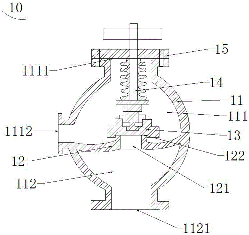
technical field [0001] The invention relates to a grinding device and method, in particular to a grinding device applied to a valve face and a grinding method thereof. Background technique [0002] As a valve used in fluid pipelines, the globe valve is widely used because of its simple structure and good sealing performance. see figure 1 , which is a schematic structural view of the existing shut-off valve 10 . A commonly used globe valve 10 includes a valve body 11 , a valve seat 12 , a valve disc 13 , a valve stem 14 and a valve cover 15 . The valve body 11 is provided with a cavity for accommodating fluid, and the valve seat 12 is disposed in the cavity and divides the cavity into an inflow cavity 111 and an outflow cavity 112 . The valve seat 12 is provided with a valve seat opening 121 through which the inlet cavity 111 and the outlet cavity 112 are connected. The valve flap 13 is arranged in the inlet cavity 111 of the valve body 11 and is attached to the upper sur...

Claims


Application Information

Patent Timeline
Patent Type & Authority Patents(China)
IPC IPC(8): B24B15/02B24B47/16
CPCB24B15/02B24B47/16
Inventor 王大伟裴慧雷冯木水
Owner 广州文冲船舶修造有限公司
Learn More