A wire threading trough punching mechanism

A technology for threading grooves and wires, which is applied to the field of punching mechanisms for wire threading grooves, can solve problems such as low efficiency and increase labor, and achieve the effect of preventing excessive punching.

Inactive Publication Date: 2017-01-11
ZHUMADIAN POWER SUPPLY ELECTRIC POWER OFHENAN
View PDF6 Cites 0 Cited by
  • Summary
  • Abstract
  • Description
  • Claims
  • Application Information

AI Technical Summary

Problems solved by technology

[0004] The threading trough is an existing trough body for various fixed wires, on which there are multiple positioning jacks. The existing manufacturing method is to punch holes in the middle of the threading trough plate, and then turn both sides of the threading trough plate upwards. Vertical bending is enough, but the existing drilling method generally adopts the method of manual drilling, which has low efficiency, and manual drilling is time-consuming and increases the amount of manual labor

Method used


Image

  • A wire threading trough punching mechanism
  • A wire threading trough punching mechanism

Examples


Embodiment

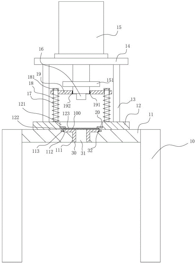
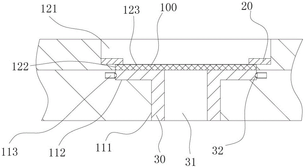
[0018] Example: see Figure 1 to Figure 2 As shown, a wire threading groove punching mechanism includes a frame 10, an oil cylinder connection base plate 12 is fixed on the platen 11 of the frame 10, and a connection pillar 13 is fixed on the top surface of the oil cylinder connection base plate 12, and the connection pillar The upper end of 13 is fixed on the upper connection plate 14, and the upper connection plate 14 is fixed with a stamping oil cylinder 15, and the push rod of the stamping oil cylinder 15 passes through the upper connection plate 14 vertically downwards, and the end of the push rod of the stamping oil cylinder 15 is screwed There is a stamping head 16, and the middle part of the oil cylinder connection base plate 12 has a stepped square hole 121, and a support rod 17 is fixed on the oil cylinder connection base plate 12. The support rod 17 is next to the step shape square hole 121, and a buffer spring is inserted in the support rod 17 18, the upper part of...


PUM


Abstract

The invention discloses an electric wire threading slot punching mechanism. The electric wire threading slot punching mechanism comprises a rack, wherein an oil cylinder connecting bottom plate is fixedly arranged on the bedplate of the rack, a connecting strut is fixedly arranged on the top surface of the oil cylinder connecting bottom plate, an upper connecting plate is fixedly arranged at the upper end of the connecting strut, a punching oil cylinder is fixedly arranged on the upper connecting plate, the push rod of the punching oil cylinder vertically and downwards penetrates through the upper connecting plate, the end portion of the push rod of the punching oil cylinder is in threaded connection with a punching head, the middle portion of the oil cylinder connecting plate is provided with a stepped square hole, a supporting rod is further fixedly arranged on the oil cylinder connecting bottom plate, the supporting rod is beside the stepped square hole, a buffer spring is inserted into the supporting rod, the upper portion of the supporting rod is inserted into a buffer plate, the top portion of the supporting rod is in threaded connection with a cap, the buffer plate is clamped ahead the buffer spring and the cap, and the lower portion of the push rod of the punching oil cylinder is inserted into a vertical insertion hole. The electric wire threading slot punching mechanism has the advantages that a wire threading slot plate can be automatically punched, the punching head and the stepped connecting head can be replaced according to the demands, and the demands for punching through holes with different diameter are satisfied.

Description

[0001] Technical field: [0002] The invention relates to the technical field of electronic parts and equipment processing, and more specifically relates to a punching mechanism for wire threading slots. [0003] Background technique: [0004] The threading trough is an existing trough body for various fixed wires, on which there are multiple positioning jacks. The existing manufacturing method is to punch holes in the middle of the threading trough plate, and then turn both sides of the threading trough plate upwards. Vertical bending is enough, but the existing drilling method generally adopts the method of manual drilling, which has low efficiency, and manual drilling is time-consuming and increases the amount of manual labor. [0005] Invention content: [0006] The purpose of the present invention is to address the deficiencies of the prior art, and provide a wire threading trough punching mechanism, which can automatically punch holes in the threading trough plate, and i...

Claims


Application Information

Patent Timeline
Patent Type & Authority Patents(China)
IPC IPC(8): B26F1/02B26F1/14
CPCB26F1/02B26F1/14
Inventor 华锋
Owner ZHUMADIAN POWER SUPPLY ELECTRIC POWER OFHENAN
Why Eureka
Try Eureka