Electronic equipment pressure holding fixture

An electronic equipment and pressure clamping technology, applied in the field of electronic equipment pressure maintaining fixtures, can solve the problems of touch screen wave pattern, difficult to control foam maintaining pressure, uneven unevenness, and achieve the effect of accurate position, uniform pressure maintaining, and flat display screen.

Inactive Publication Date: 2016-11-23
HUIZHOU TCL MOBILE COMM CO LTD
View PDF7 Cites 0 Cited by
  • Summary
  • Abstract
  • Description
  • Claims
  • Application Information

AI Technical Summary

Problems solved by technology

However, the upper cover of the fixture cannot be completely consistent with the support position of the front shell because the positioning seat supporting the front shell cannot be completely consistent with the support position of the front shell, so there is a partial void in the foam. The pressure provided is difficult to control, resulting in wavy or uneven touch screens, which makes it difficult to ensure the flatness of the product and affects the appearance and use of electronic equipment

Method used


Image

  • Electronic equipment pressure holding fixture
  • Electronic equipment pressure holding fixture
  • Electronic equipment pressure holding fixture

Examples


Embodiment Construction

[0021] Hereinafter, embodiments of the present invention will be described in detail with reference to the accompanying drawings. This invention may, however, be embodied in many different forms and should not be construed as limited to the specific embodiments set forth herein. Rather, the embodiments are provided to explain the principles of the invention and its practical application, thereby enabling others skilled in the art to understand the invention for various embodiments and with various modifications as are suited to particular intended uses. In the drawings, the shapes and dimensions of elements may be exaggerated for clarity, and the same reference numerals will be used throughout to designate the same or like elements.

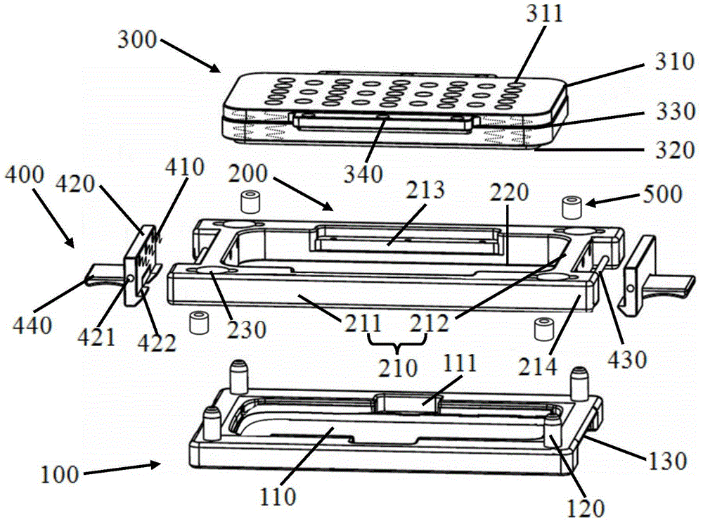
[0022] figure 1 is a schematic structural diagram of a pressure maintaining fixture for electronic equipment according to an embodiment of the present invention.

[0023] refer to figure 1 , according to the embodiment of the present invention...


PUM


Abstract

The invention discloses a pressure maintaining fixture for electronic equipment. The pressure maintaining fixture comprises a guiding plate, a positioning seat and a pressure maintaining cover; the guiding plate comprises two sets of opposite guiding walls and a limiting groove enclosed by the two sets of the opposite guiding walls, and the guiding walls are further provided with positioning holes; the positioning seat is correspondingly arranged under the guiding plate and comprises a positioning groove which is used for containing the electronic equipment and corresponds to the limiting groove and positioning pins which are arranged corresponding to the positioning holes; the pressure maintaining cover comprises a cover plate, a press head and multiple first elastic pieces, wherein the cover plate is tightly connected with the press head up and down, and the pressure maintaining cover is used for forming supporting force between the cover plate and the press head. The pressure maintaining cover is correspondingly arranged in the limiting groove and used for penetrating through the limiting groove to be in contact with the electronic equipment and exerting pressure maintaining force on the electronic equipment. According to the pressure maintaining fixture for the electronic equipment, the even pressure maintaining force can be generated on the electronic equipment which is arranged in the pressure maintaining fixture, and the position in the pressure maintaining process can be more accurate.

Description

technical field [0001] The invention belongs to the technical field of pressure holding, and in particular relates to a pressure holding fixture for electronic equipment. Background technique [0002] With the continuous development of science and technology, electronic devices play an increasingly important role in people's lives. In the manufacturing process of electronic devices, the dispensing process is used to bond two independent parts together. The dispensing process of electronic equipment is mainly to apply liquid glue on the first part, and then place the second part on the glued side of the first part. However, since the liquid glue is easy to flow, and the liquid glue needs to stand for a certain period of time before it is solidified and bonded, a pressure-holding fixture is required to clamp the first part coated with the liquid glue and the second part, so as to avoid The free flow of the applied liquid glue can better ensure the bonding effect. [0003] I...

Claims


Application Information

Patent Timeline
Patent Type & Authority Patents(China)
IPC IPC(8): B25B11/00F16B11/00
CPCB25B11/00F16B11/006
Inventor 邹群张敏
Owner HUIZHOU TCL MOBILE COMM CO LTD
Why Eureka
Try Eureka