Pressure maintaining jig, machining method of cover plate assembly, cover plate assembly and terminal device

A technology of terminal equipment and processing methods, applied in branch equipment, mechanical equipment, connecting components, etc., can solve problems that affect user experience and brand image, degumming and separation, and affect the consistency of the pressure-holding effect of glass cover components, etc., to achieve The effect of improving product quality and user experience, improving consistency, and reducing the risk of degumming

Inactive Publication Date: 2018-06-19
GUANGDONG OPPO MOBILE TELECOMM CORP LTD
View PDF4 Cites 0 Cited by
  • Summary
  • Abstract
  • Description
  • Claims
  • Application Information

AI Technical Summary

Problems solved by technology

However, when installing the fixture on the pressure holding fixture, the clamping position of the fixture is controlled by the technician, which leads to great uncertainty in the clamping position of the fixture, which will greatly affect the glass cover. The consistency of the pressure-holding effect of the plate assembly makes it easy for the glass cover plate assembly after the pressure-holding to be degummed and separated during the environmental test and drop test, which seriously affects the user experience and brand image

Method used


Image

  • Pressure maintaining jig, machining method of cover plate assembly, cover plate assembly and terminal device
  • Pressure maintaining jig, machining method of cover plate assembly, cover plate assembly and terminal device
  • Pressure maintaining jig, machining method of cover plate assembly, cover plate assembly and terminal device

Examples


Embodiment 1

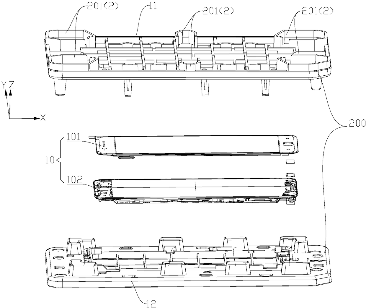
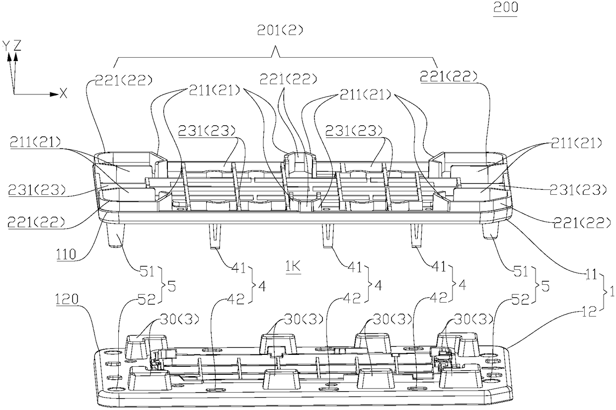
[0057] In this embodiment one, refer to Figure 1-Figure 3 The limiting structure 2 is disposed on the first cover 11 and defines a limiting groove 23 located on the side of the first cover 11 away from the second cover 12 for limiting the clip 6 . Here, for a clearer description, the limiting structure 2 provided on the first cover 11 is marked as "first limiting structure 201", and the limiting structure 2 located on the side of the first cover 11 away from the second cover 12 is The positioning groove 23 is marked as "the first limiting groove 231".

[0058] That is to say, the first limiting structure 201 is provided on the first cover body 11, that is, the first limiting structure 201 is integrally formed with the first cover body 11, or installed on the first cover body 11, the first limiting structure 201 The positioning structure 201 defines a first limiting groove 231, the first limiting groove 231 is located on the side of the first cover 11 away from the second cov...

Embodiment 2

[0062] In the second embodiment, refer to Figure 4-Figure 5 The limiting structure 2 is disposed on the second cover 12 and defines a limiting groove 23 located on a side of the second cover 12 away from the first cover 11 for limiting the clip 6 . Here, for a clearer description, the limiting structure 2 provided on the second cover 12 is marked as "second limiting structure 202", and the limiting structure 2 located on the side of the second cover 12 away from the first cover 11 is The positioning slot 23 is marked as "the second limiting slot 232".

[0063] That is to say, the second limiting structure 202 is provided on the second cover body 12, that is, the second limiting structure 202 is integrally formed with the second cover body 12, or is installed on the second cover body 12, and the second limiting structure 202 The positioning structure 202 defines a second limiting groove 232, the second limiting groove 232 is located on the side of the second cover 12 away fro...

Embodiment 3

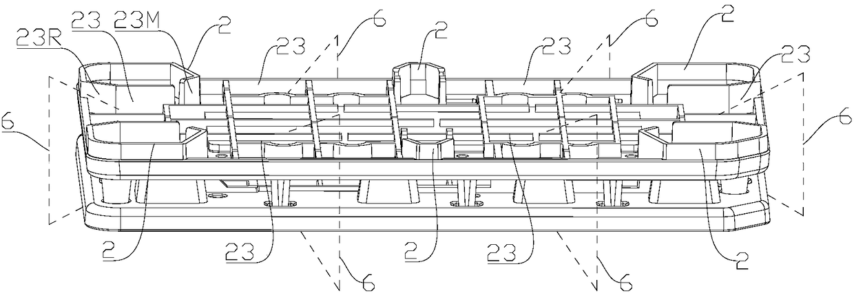
[0067] In the third embodiment, refer to Figure 6-Figure 7 , the position-limiting structure 2 is provided on the first cover 11 and the second cover 12, wherein the position-limiting structure 2 provided on the first cover 11 defines On one side, there is a limiting groove 23 for limiting the clamp 6, and the limiting structure 2 provided on the second cover 12 defines a side of the second cover 12 away from the first cover 11 for The limiting groove 23 for limiting the clip 6 is opposite to the limiting groove 23 located on both sides of the cover assembly 1 .

[0068] That is to say, in the present embodiment three, the limiting structure 2 includes both the above-mentioned first limiting structure 201 and the above-mentioned second limiting structure 202. At this time, the cover assembly 1 There are first limiting grooves 231 and second limiting grooves 232 respectively on both sides of the two sides, and the first limiting grooves 231 and the second limiting grooves 232...


PUM


Abstract

The invention discloses a pressure maintaining jig, a machining method of a cover plate assembly, the cover plate assembly and a terminal device. The pressure maintaining jig comprises a cover body assembly, a protecting structure and a limiting structure; the cover body assembly comprises a first cover body and a second cover body; the first cover body and the second cover body are oppositely arranged to define a pressure maintaining space; the protecting structure is arranged on the second cover body, and at least partially located between the first cover body and the second cover body to play an overpressure protecting role; and the limiting structure is arranged on the first cover body and defines a limiting groove located in the side, away from the second cover body, of the first cover body and used for limiting a clamp. According to the pressure maintaining jig, by designing the limiting structure to control the clamping position of the clamp, the pressure maintaining effect of the pressure maintaining jig can be improved.

Description

technical field [0001] The present invention relates to the technical field of terminal equipment, in particular to a pressure maintaining jig, a processing method for a cover plate assembly, a cover plate assembly and a terminal equipment. Background technique [0002] In the mobile phone in the related art, during the assembly process of the glass cover assembly, glue is usually used to bond the cover glass and the upper cover of the main board, and then a pressure holding fixture is used to maintain pressure on the bonded glass cover assembly. . However, when installing the fixture on the pressure holding fixture, the clamping position of the fixture is controlled by the technician, which leads to great uncertainty in the clamping position of the fixture, which will greatly affect the glass cover. The consistency of the pressure-holding effect of the plate assembly makes it easy for the glass cover plate assembly after pressure-holding to undergo environmental tests and ...

Claims


Application Information

Patent Timeline
Patent Type & Authority Applications(China)
IPC IPC(8): F16B11/00H04M1/02
CPCF16B11/006H04M1/026
Inventor 屈奔
Owner GUANGDONG OPPO MOBILE TELECOMM CORP LTD
Why Eureka
Try Eureka