
Flange component strengthened at root of flexible waveguide rubber sheath

A technology of rubber sheath and soft waveguide, applied in waveguide-type devices, electrical components, circuits, etc., can solve the problems of metal flange and rubber cracking, and achieve the effect of improving cost advantages, reducing the risk of degumming, and reducing costs.

Active Publication Date: 2019-06-04
上海阖煦微波技术有限公司
View PDF13 Cites 0 Cited by
  • Summary
  • Abstract
  • Description
  • Claims
  • Application Information

AI Technical Summary

Problems solved by technology

[0003] In order to solve the problem of cracking between the metal flange and rubber of the flexible waveguide, improve the strength of the combination of the metal flange and the rubber, and further improve the reliability of the flexible waveguide product, the present invention provides a new flange structure

Method used


Image

  • Flange component strengthened at root of flexible waveguide rubber sheath
  • Flange component strengthened at root of flexible waveguide rubber sheath
  • Flange component strengthened at root of flexible waveguide rubber sheath

Examples


Embodiment 1

[0029] Such as figure 1 As shown, the flange member reinforced at the root of the soft waveguide rubber sheath includes: a flange body 41 , a rubber engagement ring 42 , a groove 421 , and a plurality of rubber locking holes 422 .

[0030] The flange body 41 is sheet-shaped with a waveguide hole 100 in the middle.

[0031] The rubber engaging ring 42 is fixedly arranged on one side surface of the flange body 41 , and the shape of the rubber engaging ring 42 is ring. Such as figure 1 As shown, a first bonding area 43 is formed between the ring and the flange body.

[0032] The groove 421 is opened on the inner side of the connection between the rubber joint ring 42 and the flange body.

[0033] A plurality of rubber locking holes 422 are longitudinally opened and distributed on the inner wall of the rubber engagement ring, communicating with the groove 421 .

[0034] The rubber sheath 14 is connected with the rubber engaging ring 42, such as image 3 As shown, the rubber i...

Embodiment 2

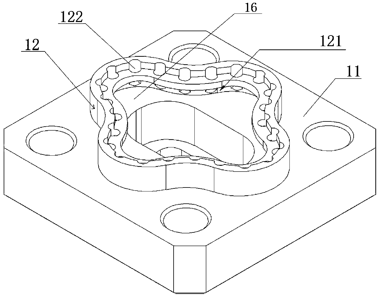
[0036] Such as figure 2 As shown, the flange member reinforced at the root of the soft waveguide rubber sheath includes: a flange body 11 , a rubber joint ring 12 , a groove 121 , and a plurality of rubber locking holes 122 .

[0037] The flange body 11 is sheet-shaped with a waveguide hole in the middle.

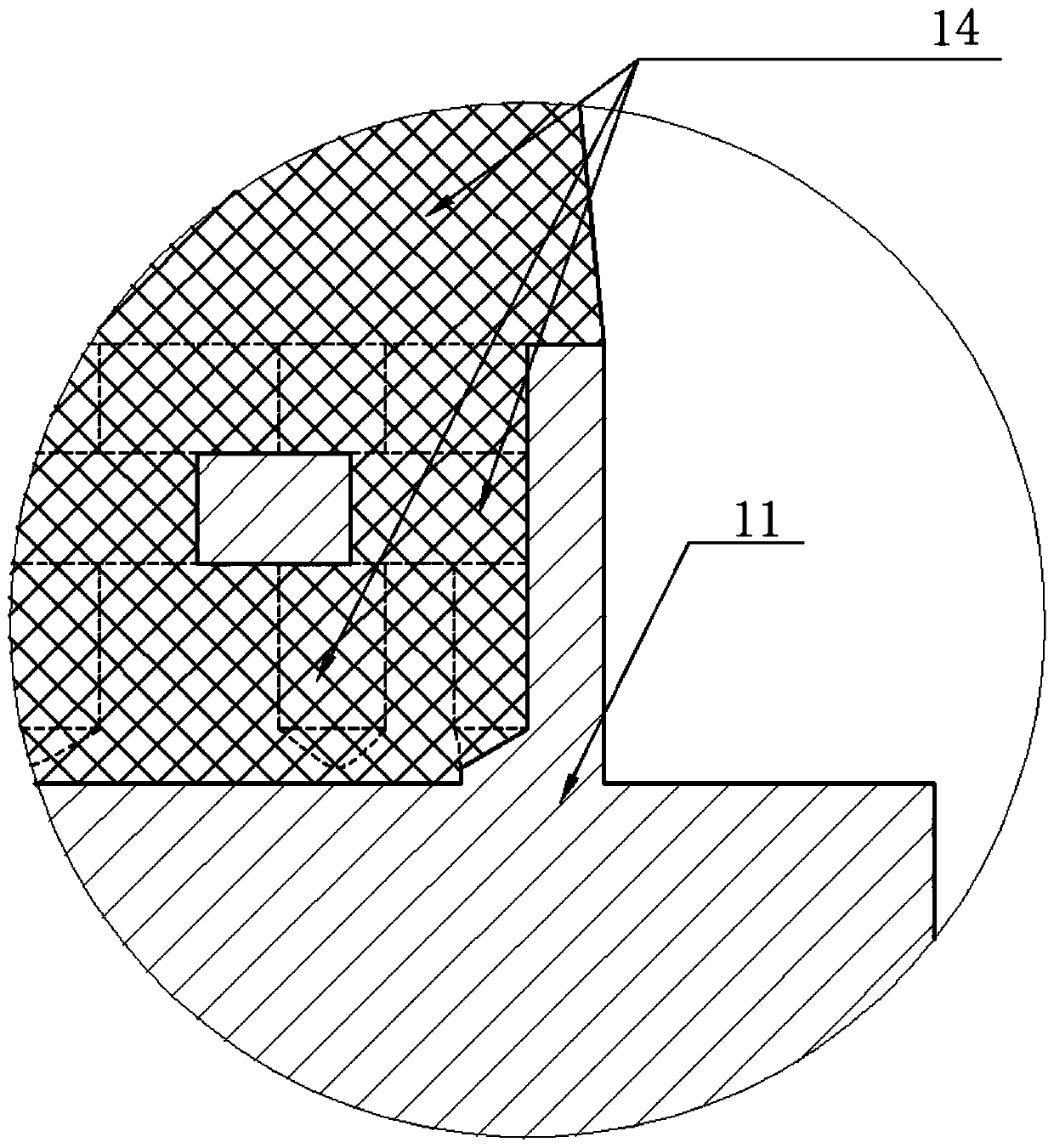
[0038] The rubber joint ring 12 is fixedly arranged on one side surface of the flange body 11 , and the shape of the rubber joint ring 12 is a hollow cross. Such as figure 2 and Figure 5 As shown, a second bonding area 16 is formed between the hollow cross and the flange body. The area of ​​the second bonding area 16 is as Figure 5 Shown in the shaded part.

[0039] The groove 121 is opened on the inner side of the connection between the rubber joint ring 12 and the flange body.

[0040] A plurality of rubber locking holes 122 are longitudinal holes distributed on the inner wall of the rubber engagement ring and communicated with the groove 121 .

[0041] The rub...

Embodiment 3

[0045] Such as Figure 7 As shown, the shape of the rubber joint ring 22 is generally a rectangle, but at the four sides of the rectangle, there are outwardly protruding arcs, and a third bonding area 24 is formed between the outwardly protruding arcs and the flange body. A plurality of rubber locking holes 23 are also opened on the rubber engaging ring 22 .

[0046] The connection mode between the flange body and the rubber sheath in this embodiment is the same as that in the above two embodiments.

[0047] In this embodiment, also, the rubber in the rubber sheath can be poured into the groove and the rubber locking hole 23 . Therefore, the connection between the rubber sheath and the flange body 21 is more firm.

[0048] The traditional flange structure needs to process multiple surfaces, and multiple clamping and positioning are required during processing, and the processing process is cumbersome. In this embodiment, a traditional rectangular flange is taken as an exampl...


PUM


Abstract

The invention provides a flange component strengthened at the root of a flexible waveguide rubber sheath. The flange component is characterized by comprising a flange body, a rubber joint ring fixedlyarranged on one side surface of the flange body, a groove arranged in the inner side of the junction of the between rubber joint ring and the flange body, and multiple rubber lock holes longitudinally distributed on the inner wall of the rubber joint ring and communicated with the groove. By using the flange component, the problem of cracking caused by insufficient bonding strength between rubberand metal at the foot of a flange is solved, and moreover, the reliability of soft waveguide products is improved, the service life of soft waveguide products is prolonged, and the risk of degummingbetween a metal flange and a rubber sheath of a soft waveguide product under extreme environmental conditions is reduced.

Description

technical field [0001] The invention relates to a flange component reinforced at the root of a soft waveguide rubber sheath, which belongs to the field of communication equipment. Background technique [0002] At present, the joint between the root of the flexible waveguide flange and the rubber sheath is bonded with a special rubber primer to ensure the reliability of the joint. Although some flanges increase the bonding area by adding grooves, and finally achieve the purpose of enhancing the bonding strength, but due to the performance limitations of the primer itself, as well as the brand of the primer, the factory production batch, changes in the storage and transportation environment, The differences in brushing methods lead to poor consistency of the bonding effect between the flexible waveguide metal flange and the rubber sheath, unreliable product life, and the risk of debonding between the metal flange and the rubber sheath under extreme environmental conditions. ...

Claims


Application Information

Patent Timeline
Patent Type & Authority Applications(China)
IPC IPC(8): H01P1/04
Inventor 顾春健李慧勇周秋月丰国琴王欣丰杨婷婷
Owner 上海阖煦微波技术有限公司
Learn More