Integrated driving system of electric car

A drive system, electric vehicle technology, applied in electric vehicles, electric traction, electrical devices, etc., can solve problems such as hidden safety hazards, and achieve the effects of improving inheritance, reducing costs, and reducing possibilities

CN104908599AInactive Publication Date: 2015-09-16马军 +1
6 Cites 3 Cited by

Patent Information

Authority / Receiving Office
CN · China
Patent Type
Applications(China)
Current Assignee / Owner
Publication Date
2015-09-16
Estimated Expiration
Not applicable · inactive patent

Smart Images

  • Figure 1
    Figure 1
  • Figure 2
    Figure 2
  • Figure 3
    Figure 3
Patent Text Reader

Abstract

The invention provides an integrated driving system of an electric car, which is characterized in that the driving system comprises a high voltage case, a motor controller, a charging set, a direct-current converter and an electric appliance case body; the high voltage case, the motor controller, the charging set and the direct-current converter are assembled in the electric appliance case body in a unified and integrated manner; electric and electronic parts are connected in the electric appliance case body and conduct insulation protection; and a driving motor is directly fixed on the electric appliance case body to form integral hoisting and disassembly, and is mounted in a forward engine room in the car. The system integrates all high voltage electrical apparatus parts, provides a constant temperature environment condition, and has no exposed high voltage wires, so that the possibility of burning due to short circuit resulting from car collision is reduced greatly; the integral assembly and disassembly are realized; a loading space and reasonable support are considered integrally; the system is improved in the aspects of design and layout of the complete car, manufacturing and maintenance, cost reduction, economic performance improvement, mass production convenience, etc.; the succession of the traditional car is improved greatly; and the electrification course of the traditional car is accelerated.
Need to check novelty before this filing date? Find Prior Art

Description

technical field

[0001] The invention belongs to the technical field of electric vehicles, and more specifically relates to an integrated drive system for electric vehicles. Background technique

[0002] Petroleum resources and environmental pollution issues have attracted great attention from governments and all walks of life around the world. Electric vehicles have become the future development direction of the automotive industry due to their advantages such as zero emissions, high efficiency, convenient driving, comfortable operation, and extensive power sources. However, most of the current electric vehicles are refitted on the basis of the original car body, which belong to modified or assembled electric vehicles. But there are problems in cost, quality and safety. For example: the scattered electrical components in the front cabin include motor controllers, chargers, DC converters, electric air conditioners, electric vacuum pumps, high and low voltage distribution box...

Examples

Embodiment Construction

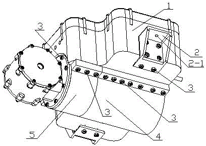
[0009] figure 1 It is a schematic diagram of an integrated drive system of an electric vehicle according to the present invention. In the figure, 1 is the electrical box, 2 is the bracket of the electrical box, 2-1 is the external mounting hole of the bracket of the electrical box, and 3 is the mounting bolt of the bracket of the electrical box , the connection bolt 3 of drive motor 4 and electric box body 1 and the bolt connection 3 of speed reducer 5 and electric box body 1 in similar figure can use same bolt, and 4 is drive motor, and 5 is speed reducer.

[0010] figure 2 It is an exploded schematic view of the integrated drive system of the present invention. 1-1 in the figure is the lower body of the electrical box 1, 1-2 in the figure is the upper cover of the electrical box 1, and the battery box 1 is equipped with a high-voltage box 6, a DC converter 7, a charger 8, and a motor controller 9. Among the figure 4-1 is the junction box of the drive motor 4, 4-2 is the ...