Power distribution cabinet with movable rollers

A technology for moving rollers and power distribution cabinets, applied in substation/power distribution device shells, electrical components, substation/switch layout details, etc., can solve problems such as impact, safety hazards, noise, etc., to avoid impact and run Reliable, easy-to-use results

Inactive Publication Date: 2015-09-23
慈溪市隆诚贸易有限公司
View PDF0 Cites 0 Cited by
  • Summary
  • Abstract
  • Description
  • Claims
  • Application Information

AI Technical Summary

Problems solved by technology

The closing of the door often requires the operator to perform additional operations to lock, and this kind of

Method used


Image

  • Power distribution cabinet with movable rollers
  • Power distribution cabinet with movable rollers
  • Power distribution cabinet with movable rollers

Examples


Embodiment Construction

[0011] Combine below Figure 1-4 The present invention will be described in detail.

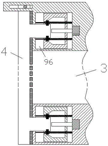
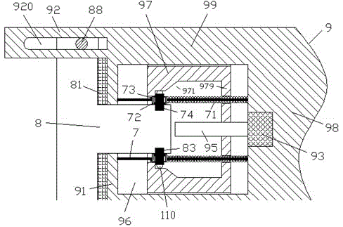
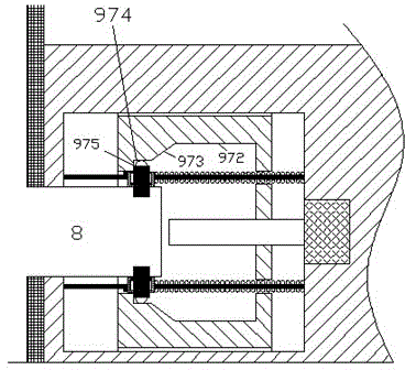
[0012] According to the embodiment of the distribution cabinet with moving rollers, it includes a cabinet body 3 with a locking socket device 9 at the frame and a door panel 4 with a cylindrical locking protruding plug 8 at the corresponding edge, the locking protruding Outlet plug 8 is intended to be inserted into a cavity 96 of said locking socket arrangement 9 comprising an end wall 91, a lateral side wall 99 and a body 98 opposite said end wall 91 so that Enclosing the cavity 96, the side of the door panel 4 facing the cabinet body 3 is provided with an elastic sealing layer 81 for joining with the outside of the end wall 91, and the cavity 96 is provided with a The inner side of the end wall 91 and a plurality of guide columns 7 fixedly connected with the body 98, the guide columns 7 are slidably loaded with a locking slider assembly 72, and the locking slider assembly 72 is provided wi...


PUM


Abstract

A power distribution cabinet with movable rollers comprises a cabinet body (3) with locking jack apparatuses (9) at borders, and a door plate (4) with cylindrical locking protruding plugs (8) at corresponding edges, wherein the locking protruding plugs (8) are inserted into cavities (96) of the locking jack apparatuses (9); and each locking jack apparatus (9) comprises end walls (91), transverse side walls (99) and a body (98) opposite to the end walls (91), so that the cavities (96) are defined.

Description

technical field [0001] The application relates to the field of power distribution equipment, specifically a power distribution cabinet with moving rollers. Background technique [0002] The power distribution cabinet is often provided with power distribution components, and these components may be some power distribution components known in the art to realize the power distribution function. [0003] In order to facilitate the user's operation, the power distribution cabinet often has a door that can be opened and closed. The closing of the door often requires the operator to perform additional operations to lock, and this kind of locking is often a kind of impact snap lock, which is easy to cause impact force and noise, and poses a safety hazard. Contents of the invention [0004] The object of the present invention is to provide a power distribution cabinet with moving rollers, which can solve the above-mentioned problems in the prior art. [0005] According to the pre...

Claims


Application Information

Patent Timeline
IPC IPC(8): H02B1/26E05C1/08E06B7/22
CPCH02B1/30E06B7/22H02B1/303H02B1/38
Inventor 丁文龙
Owner 慈溪市隆诚贸易有限公司
Why Eureka
Try Eureka