Power distribution cabinet with roller grooves

A technology of roller grooves and power distribution cabinets, applied in substation/distribution device casings, non-mechanical transmission-operated locks, buildings, etc., can solve the problems of noise, hidden dangers, easy to cause impact force, etc. Reliable, shock-avoiding effect

Inactive Publication Date: 2015-09-30
衢州磊巨电子科技有限公司
View PDF3 Cites 0 Cited by
  • Summary
  • Abstract
  • Description
  • Claims
  • Application Information

AI Technical Summary

Problems solved by technology

The closing of the door often requires the operator to perform additional operations to lock, and this kind of lock is often a kind of impact snap lock, which is easy to cause impact force and noise, forming a safety hazard

Method used


Image

  • Power distribution cabinet with roller grooves
  • Power distribution cabinet with roller grooves
  • Power distribution cabinet with roller grooves

Examples


Embodiment Construction

[0011] Combine below Figure 1-4 The present invention will be described in detail.

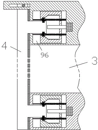
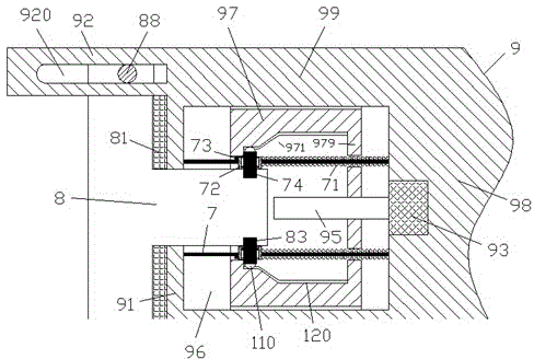
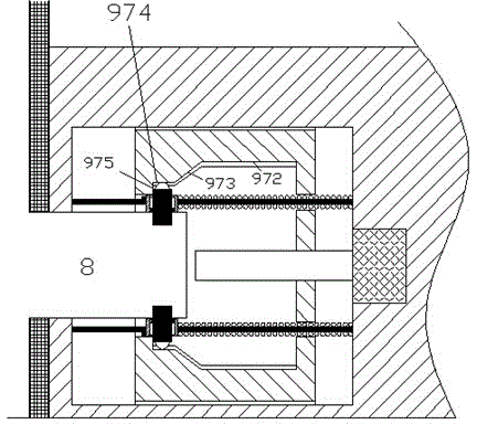
[0012] According to the embodiment of the distribution cabinet with roller slots, it includes a cabinet body 3 with a locking socket device 9 at the frame and a door panel 4 with a cylindrical locking protruding plug 8 at the corresponding edge, the locking protruding Outlet plug 8 is intended to be inserted into a cavity 96 of said locking socket arrangement 9 comprising an end wall 91, a lateral side wall 99 and a body 98 opposite said end wall 91 so that Enclosing the cavity 96, the side of the door panel 4 facing the cabinet body 3 is provided with an elastic sealing layer 81 for joining with the outside of the end wall 91, and the cavity 96 is provided with a The inner side of the end wall 91 and a plurality of guide columns 7 fixedly connected with the body 98, the guide columns 7 are slidably loaded with a locking slider assembly 72, and the locking slider assembly 72 is provided with...


PUM


Abstract

A power distribution cabinet with roller grooves comprises a cabinet body (3) provided with locking insertion devices (9) on a frame and a door plate (4) provided with cylindrically locking bulge insertion heads (8) on the corresponding edges, wherein the locking bulge insertion heads (8) are inserted into cavities (96) of the locking insertion hole devices (9), each locking insertion hole device (9) comprises an end wall (91), a horizontal side wall (99) and a body (98) opposite to the end wall (91), and accordingly, the cavities (96) are defined.

Description

technical field [0001] The application relates to the field of power distribution equipment, in particular to a power distribution cabinet with roller grooves. Background technique [0002] The power distribution cabinet is often provided with power distribution components, and these components may be some power distribution components known in the art to realize the power distribution function. [0003] In order to facilitate the user's operation, the power distribution cabinet often has a door that can be opened and closed. The closing of the door often requires the operator to perform additional operations to lock, and this kind of locking is often a kind of impact snap lock, which is easy to cause impact force and noise, and poses a safety hazard. Contents of the invention [0004] The object of the present invention is to provide a power distribution cabinet with a roller groove, which can solve the above-mentioned problems in the prior art. [0005] According to th...

Claims


Application Information

Patent Timeline
Patent Type & Authority Applications(China)
IPC IPC(8): H02B1/26E06B7/16E05B65/00E05B63/14E05B47/00
Inventor 不公告发明人
Owner 衢州磊巨电子科技有限公司
Why Eureka
Try Eureka