Converter systems and wind or hydroelectric power plants

A technology of wind power generation equipment and flow system, applied in the field of variable flow system, can solve problems that cannot be easily realized

Active Publication Date: 2017-10-24
KEBA IND AUTOMATION GERMANY GMBH
View PDF2 Cites 0 Cited by
  • Summary
  • Abstract
  • Description
  • Claims
  • Application Information

AI Technical Summary

Problems solved by technology

In contrast, this cannot be easily achieved in AC motors

Method used


Image

  • Converter systems and wind or hydroelectric power plants
  • Converter systems and wind or hydroelectric power plants

Examples


Embodiment Construction

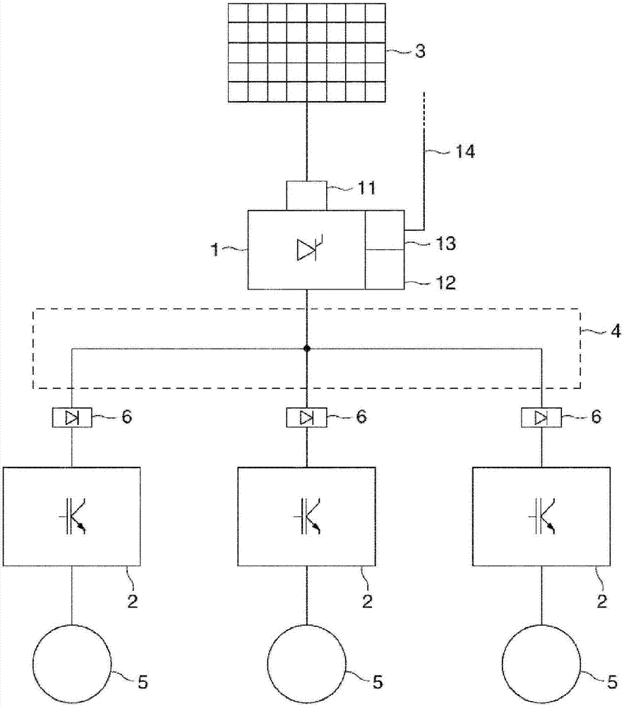
[0022] figure 1 A converter system according to the invention is shown with a rectifier 1 and three inverters 2 . This rectifier 1 is connected to an AC power source 3, and the AC power source can be constituted by a power grid or the like. The rectifier 1 rectifies the three-phase alternating current supplied by the alternating current power source 3 and supplies it to the inverter 2 through the direct current circuit 4 . The inverter 2 is connected to an electrical appliance 5 , and the electrical appliance 5 is powered by the inverter 2 . These consumers may include DC motors or AC motors, etc. In each connection of the inverter 2 to the DC circuit 4 there is provided a decoupling device 6 which prevents the transfer of electrical energy from the inverter 2 in the direction of the DC circuit 4 . The rectifier 1 has an overvoltage protection 11 on the input side, and the overvoltage protection 11 protects the converter system of the present invention from overvoltage orig...


PUM


Abstract

The invention describes and shows a converter system with a rectifier (1) and at least two inverters (2), wherein the rectifier (1) can be powered by an alternating current source (3), the rectifier (1 ) is connected to each inverter (2) through a shared DC circuit (4) so ​​as to supply power to the inverter (2), and each inverter (2) can be connected to the electrical appliance ( 5) connected to each other so as to supply power to the electrical appliances (5). A particularly reliable converter system is achieved according to the invention in that a decoupling device (6) is provided in at least one connection between the DC circuit (4) and the one inverter (2), the The decoupling device (6) prevents the transmission of electric energy from the inverter (2) in the direction of the direct current circuit (4). Also described and shown is a wind or hydroelectric power plant with a rotor having a rotor hub and at least two rotor blades which can be surrounded by their respective longitudinal Axis rotation. A particularly reliable wind or hydroelectric power plant is achieved according to the invention in that the wind or hydro power plant has a power conversion system according to any one of claims 1 to 11, wherein the power conversion system feeds the consumers (5) Power supply.

Description

technical field [0001] The present invention relates to a converter system having a rectifier and at least two inverters, wherein the rectifier can be powered by an alternating current source, the rectifier is connected to each inverter through a common direct current circuit to supply power to the inverters, and each The inverters can be connected to the electrical appliances respectively so as to supply power to each electrical appliance. [0002] Furthermore, the invention relates to a wind or hydroelectric power plant with a rotor, wherein the rotor has a rotor hub and at least two rotor blades, which can be rotated about a respective longitudinal axis by means of electrical consumers. Background technique [0003] US 7,126,236 B2 discloses a method and a system for powering at least one DC motor of a wind power plant, the system having a bridge rectifier connected to the power supply, in order to generate a DC voltage and to supply this DC voltage to the aforementioned ...

Claims


Application Information

Patent Timeline
Patent Type & Authority Patents(China)
IPC IPC(8): H02M5/458H02M7/48
CPCH02M5/458H02M7/48H02M1/008Y02E10/76Y02E10/20Y02E10/72F03D7/042F03B15/00H02H7/1222
Inventor 托拜厄斯·特奥波特马赛厄斯·泡利雷·奥佩
Owner KEBA IND AUTOMATION GERMANY GMBH
Why Eureka
Try Eureka