
Real-time pump diagnostic algorithms and application thereof

A near real-time, diagnostic technology used in pump diagnostics to solve problems such as time delays

Active Publication Date: 2015-09-30
LUFKIN INDUSTRIES
View PDF12 Cites 6 Cited by
  • Summary
  • Abstract
  • Description
  • Claims
  • Application Information

AI Technical Summary

Problems solved by technology

There is a time delay between displaying the pump card and displaying the surface card

Method used


Image

  • Real-time pump diagnostic algorithms and application thereof
  • Real-time pump diagnostic algorithms and application thereof
  • Real-time pump diagnostic algorithms and application thereof

Examples


Embodiment Construction

[0050] Specific embodiments of the present invention may be described below with reference to block diagrams and operational illustrations of methods. It will be understood that each block of the block diagrams and their operational illustrations, and combinations of blocks of the block diagrams and their operational illustrations, can be implemented by both analog and digital hardware and computer program instructions. Such computer program instructions can be provided to processors of general purpose computers, special purpose computers, ASICs and other programmable data processing systems. The instructions executed create the structures and functions for implementing the actions specified in the block diagrams and operational illustrations. In some alternative implementations, the functions / acts / structure noted in the figures may occur out of the order noted in the block diagrams and operational illustrations. For example, two operations shown as occurring in succession ...


PUM


Abstract

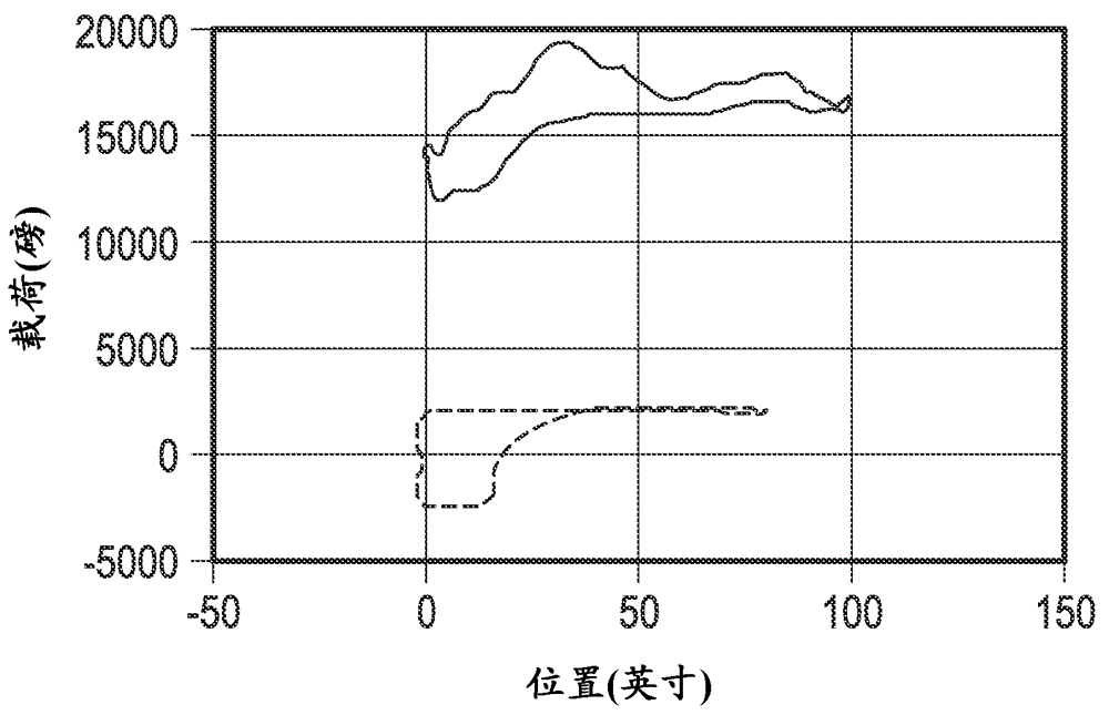
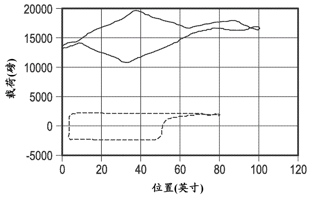
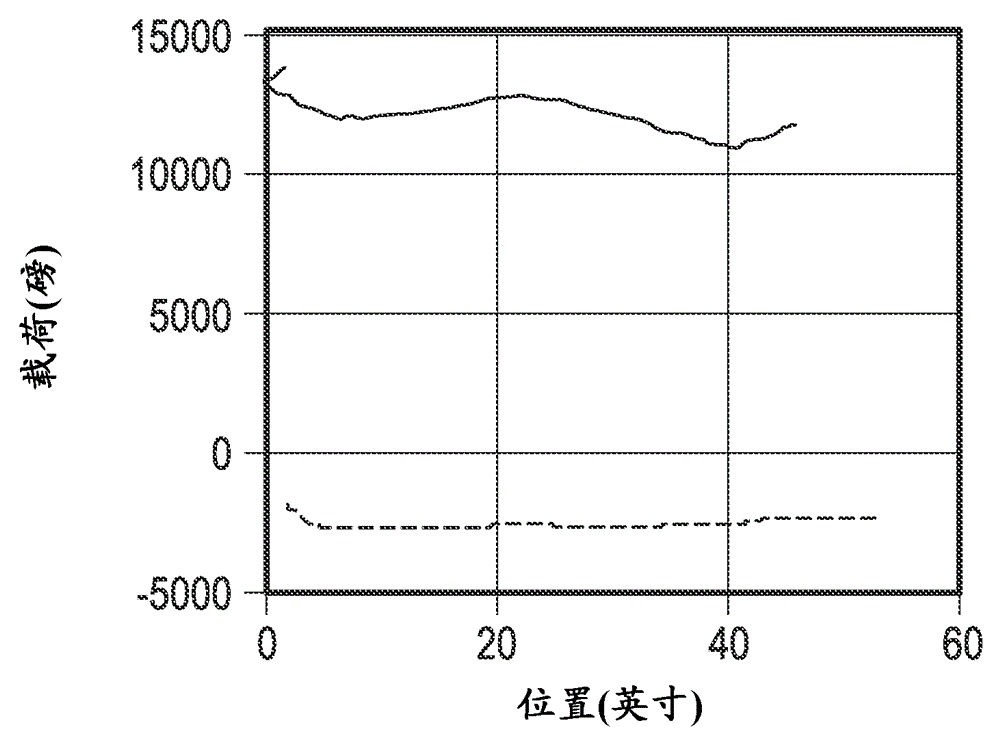
A method for determining a pump card for a well. The method comprising: obtaining a first set of data points, wherein the first set of data points comprise a first set of polished rod position data points of the well and a first set of polished rod load data points of the well; and calculating a first data point of a pump position and a pump load using the first set of data points. The calculating occurs before the well moves through a first complete stroke cycle.

Description

[0001] Cross References to Related Applications [0002] This application claims the benefit of priority to US Provisional Patent Application Serial No. 61 / 727894, filed November 19, 2012, the contents of which are hereby incorporated by reference in their entirety. [0003] Statement on Federal Funding for Research and Development [0004] Not applicable. [0005] Appendix Reference [0006] Not applicable. technical field [0007] FIELD OF THE INVENTION The invention disclosed and taught herein relates generally to pump diagnostic methods, and more particularly to real-time and near-term diagnostics for use with rod pumps and similar well pumping systems. Real-time pump diagnostic techniques and approaches. Background technique [0008] Modern pump diagnostic techniques for straight wells originated with Gibbs in 1966 [Gibbs S. G et al., Journal of Petroleum Technology, Vol. 18(1), pp. 91-98 (1966)]. Gibbs used a separation of variables approach to generate an explici...

Claims


Application Information

Patent Timeline
Patent Type & Authority Applications(China)
IPC IPC(8): E21B47/009
CPCE21B47/0008E21B47/0007E21B47/09F04B47/02F04B49/065E21B47/009E21B47/008
Inventor Z.陈D.多拉多E.厄斯特雷奇G.休斯A.科尔多瓦
Owner LUFKIN INDUSTRIES
Learn More