Operation control method for linear compressor

A linear compressor and operation control technology, applied in pump control, mechanical equipment, machine/engine, etc., can solve problems such as lack of connecting rods, unstable pressure, etc., to reduce energy consumption, increase down rate, and prevent damage Effect

Inactive Publication Date: 2009-02-04
TAIZHOU LG ELECTRONICS REFRIGERATOR CO LTD
View PDF4 Cites 0 Cited by
  • Summary
  • Abstract
  • Description
  • Claims
  • Application Information

AI Technical Summary

Problems solved by technology

[0002] Generally speaking, the existing linear compressors are driven by free pistons and do not have connecting rods to constrain the movement of the pistons. The movement state of the pistons is determined by the pressure inside the compression chamber, the stiffness of the resonant spring, the mass of the pistons and the drive motor. determined by the excitation force
In addition, the pressure inside the compression chamber of the existing linear compressor is nonlinear, and the output pressure is unstable

Method used


Image

  • Operation control method for linear compressor
  • Operation control method for linear compressor
  • Operation control method for linear compressor

Examples


Embodiment 1

[0037] Figure 3a It is a flow chart of Embodiment 1 of the operation control method of the linear compressor of the present invention.

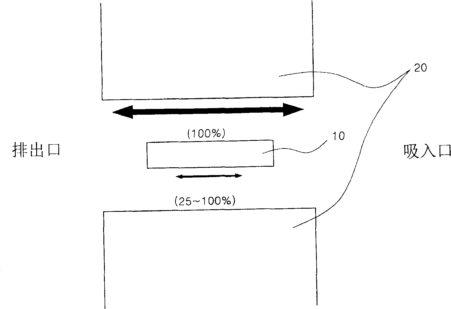
[0038] After the linear compressor is energized and started, the piston (10) inside the compressor starts to reciprocate. In the present invention, by setting the elapsed time of the pressure-holding stroke cycle and the full stroke cycle and the reciprocating range value of the piston (10), The piston (10) is driven and controlled to perform reciprocating motion within a set range.

[0039] Specifically, as Figure 3a As shown, the operation control method of the linear compressor of the present invention includes:

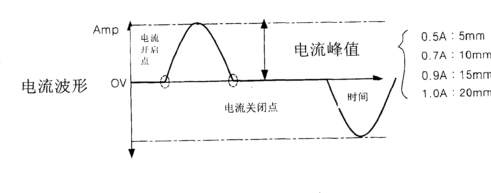
[0040] The 100th stage: the input power makes the piston (10) start to reciprocate. At this time, in order to judge whether the piston (10) is driven within the set range of the full stroke, the input compression is sensed during the reciprocating motion of the piston during the pressure-holding stroke cycle. The current val...

Embodiment 2

[0047] Figure 3b It is a flow chart of Embodiment 2 of the operation control method of the linear compressor of the present invention; Embodiment 2 is described in detail below:

[0048] After the linear compressor is energized and started, the piston (10) inside the compressor starts to reciprocate. In the present invention, by setting the elapsed time of the pressure-holding stroke cycle and the full stroke cycle and the reciprocating range value of the piston (10), The piston (10) is driven and controlled to perform reciprocating motion within a set range.

[0049] Specifically, as Figure 3b As shown, the operation control method of the linear compressor of the present invention includes:

[0050] The 200th stage: input power to make the piston (10) start reciprocating;

[0051] The 210th stage: the reciprocating motion of the piston (10) will reach the full stroke cycle after the specified time;

[0052] Stage 220: If the time from the start of the reciprocating motion...

Embodiment 3

[0057] Fig. 3c is a flow chart of Embodiment 3 of the operation control method of the linear compressor of the present invention.

[0058] As shown in Figure 3, the operation control method of the linear compressor of the present invention includes:

[0059] Stage 300: After the power is input, the piston (10) starts to reciprocate. At this time, the control unit (not shown in the figure) presets the current value and stroke input to the compressor when the piston (10) reaches the starting point of the discharge pipe. the phase difference;

[0060] Stage 310: Next, measure the current value of the current input compressor and the stroke phase difference, and compare the measured current value and stroke phase difference of the current input compressor with the preset current value and stroke phase difference respectively. Comparison, through the above comparison, when it is judged that the piston (10) has reached the discharge pipe, then perform the 320th stage downward; when...


PUM


Abstract

The operation control method of linear compressor includes: the first stage of turning on the power source to make the piston to reciprocate in the pressure maintaining stroke period smaller than the maximum reciprocating period within the first time range; the second stage of making the piston in the complete stroke period range; and the third stage of making the piston to move to reach the exhaust pipe. The present invention has the beneficial effects of stable driving of the piston in the linear compressor to avoid damage to parts, low noise, low power consumption and optimal drive state of the linear compressor.

Description

technical field [0001] The invention relates to an operation control method of a linear compressor, in particular to an operation control method of a linear compressor which controls the working state of the compressor by setting the reciprocating time and stroke range of the piston. Background technique [0002] Generally speaking, the existing linear compressors are driven by free pistons and do not have connecting rods to constrain the movement of the pistons. The movement state of the pistons is determined by the pressure inside the compression chamber, the stiffness of the resonant spring, the mass of the pistons and the drive motor. determined by the excitation force. In addition, the pressure inside the compression chamber of the existing linear compressor is non-linear, and the output pressure is unstable. Contents of the invention [0003] The technical problem to be solved by the present invention is to overcome the above-mentioned shortcomings of the existing l...

Claims


Application Information

Patent Timeline
Patent Type & Authority Patents(China)
IPC IPC(8): F04B49/12F04B49/06
Inventor 玉正琨
Owner TAIZHOU LG ELECTRONICS REFRIGERATOR CO LTD
Why Eureka
Try Eureka