
Motorcycle headlight device

a headlight device and motorcycle technology, applied in the direction of lighting support devices, cycle equipment, lighting and heating apparatus, etc., can solve the problems of delay in the operation of the headlight module, the headlight device such as discussed above has a problem, and the proper illumination is indeed prominent, so as to prevent slippage, reduce the effect of affecting the operation speed and the durability of the drive unit of the light-distribution adjusting mechanism

Active Publication Date: 2008-05-15
KAWASAKI MOTORS LTD
View PDF3 Cites 30 Cited by
  • Summary
  • Abstract
  • Description
  • Claims
  • Application Information

AI Technical Summary

Benefits of technology

[0010]In view of the foregoing, the present invention has been devised to substantially eliminate the problems and inconveniences inherent in the prior art headlight devices and is intended to provide a headlight device, in which a change of the region of illumination afforded by the headlamp module can be initiated substantially punctual to the start of cornering of the motorcycle. Another important object of the present invention is to provide a headlight device of the type referred to above, in which the region of illumination afforded by the headlamp module can be changed to secure a required reach of the illumination at all times regardless of the tilt of the motorcycle.

Problems solved by technology

However, the motorcycle headlight device such as discussed above has been found having a problem.
For this reason, the headlamp module is rotated or pivoted with a certain length of time delayed relative to the banking of the motorcycle and, therefore, at an initial stage, in which the motorcycle starts banking, distribution of light cast by the headlamp module would not result in a proper illumination sufficient to allow the motorcycle drive to enjoy a relatively large field of view forwardly of the motorcycle.
This delay in operation of the headlamp module is indeed prominent particularly where the motorcycle is maneuvered with legerity such as occurring during traveling in, for example, a zigzag course.

Method used


Image

  • Motorcycle headlight device
  • Motorcycle headlight device
  • Motorcycle headlight device

Examples


first embodiment

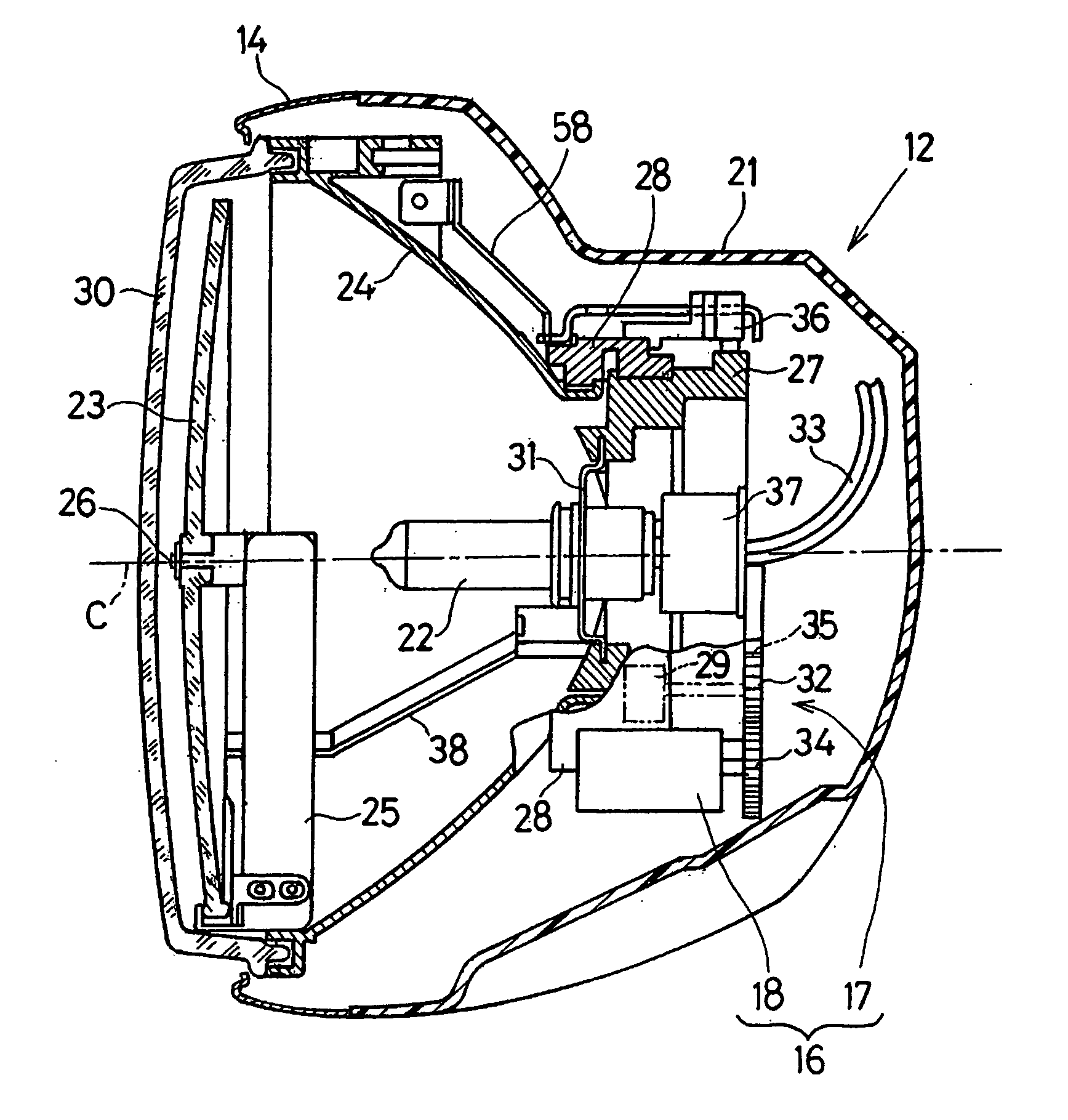
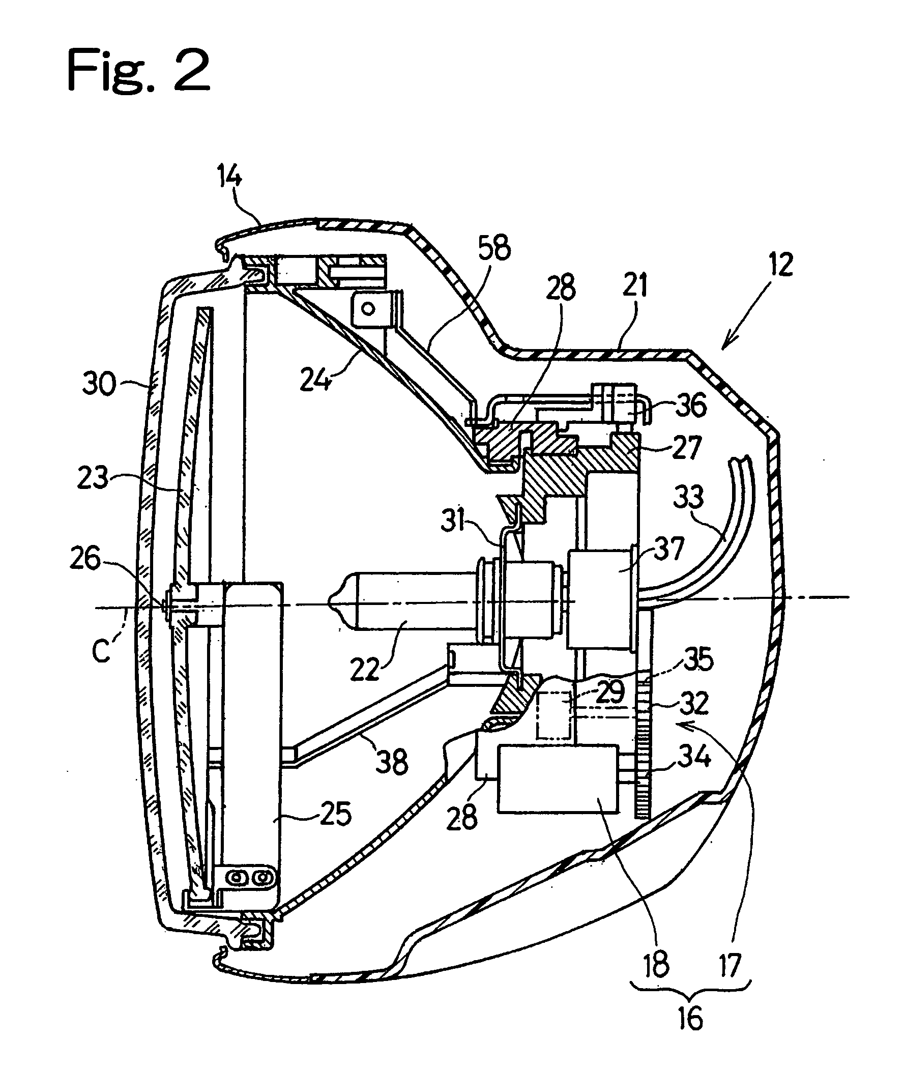
[0080]It is to be noted that although in the foregoing first embodiment of the present invention, the combination of the lens 23 and the bulb 22 shown in FIG. 2 has been described as being turned an angle corresponding to the magnitude of the motorcycle bank angle δ, the reflector 24, for example, may be turned particularly where the reflector 24 is so designed as to have a light distributing capability.

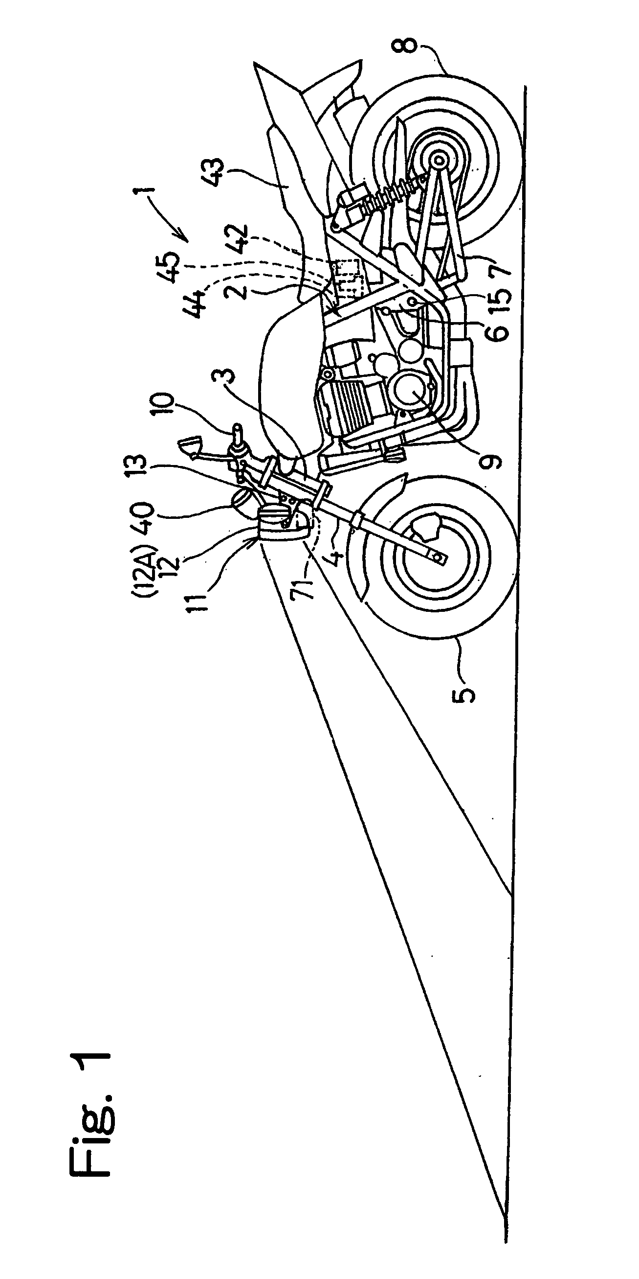
[0081]Also, in a modification of the foregoing first embodiment, the standard headlamp module of a fixed type, in which the light-distribution adjusting mechanism 16 is eliminated from the headlamp module 12 shown in FIG. 2, is used as a principal headlamp unit 12A, to which left and right auxiliary headlamp units 71 shown by the double dotted line in FIG. 1 are added to form the headlight device 11. The left auxiliary headlamp unit 71 is so designed that the illumination afforded by the left auxiliary headlamp unit 71 can reach further leftward away from the motorcycle than the illu...

fourth embodiment

[0097]For the reason discussed above, the distance of reach of the illumination from the headlamp module 51 when the motorcycle is banked represents a value D1 as shown in FIG. 17, which is smaller than the distance of reach D thereof exhibited during the straight forward run of the motorcycle, by a quantity corresponding to the difference between the heights H and X of the headlamp module 51 above the road surface, failing the headlamp module 51 to cast illumination sufficiently further away from the motorcycle. In view of this, in the present invention, arrangement has been so made that when the height of the headlamp module 51 decreases during the cornering, the headlamp module 51 can be tilted upwardly an angle ø corresponding to the bank angle δ of the motorcycle. By so doing, the region of illumination A shown in FIG. 18 can be shifted further away from the motorcycle substantially in parallel to the mid-center plane BC of the motorcycle to render the distance of reach of the ...


PUM


Abstract

To provide a headlight device, in which a change of the region of illumination afforded by the headlamp can be initiated substantially punctual to the start of cornering of the motorcycle, the headlight device includes a headlamp for illuminating forwardly of the motorcycle, a light-distribution adjusting mechanism for changing a region of illumination, a bank angle detecting unit for detecting a bank angle δ of the motorcycle in reference to an angular velocity ωy about a vertical axis of the motorcycle, an angular velocity ωr about a longitudinal axis of the motorcycle and a motorcycle velocity v, and a light-distribution controller for controlling the light-distribution adjusting mechanism based on the detected bank angle δ to change the region of illumination into an area further away from and at least inwardly of a direction of turn of the motorcycle during a cornering.

Description

BACKGROUND OF THE INVENTION[0001](Field of the Invention)[0002]The present invention relates to a headlight device for a motorcycle, which is designed to permit a motorcycle rider to gain a relatively large illuminated field of view forwardly of the motorcycle while the latter makes the curve during a night drive.[0003](Description of the Prior Art)[0004]As is well known to those skilled in the art, the motorcycle, when ready to change the direction of travel either leftward or rightward with respect to the direction of straightforward run thereof while traveling at a certain speed, is tilted or banked either leftward or rightward at a bank angle. However, considering that the headlight used in most motorcycles now in use is fixed in position to the motorcycle frame structure and, therefore, the region of illumination cast by the motorcycle headlight is correspondingly tilted as the motorcycle is banked, the amount of light distributed by the motorcycle headlight in an area inwardly...

Claims


Application Information

Patent Timeline
Patent Type & Authority Applications(United States)
IPC IPC(8): B62J6/00F21V21/28
CPCB60Q1/12B62J6/02B60Q2300/136B62J6/023B62J6/026
Inventor NAKANO, SHINICHIYAMAMOTO, YOSHINOBUDOMOTO, MIKIOBAINO, MAKOTO
Owner KAWASAKI MOTORS LTD
Learn More