
A roadway stacker for dense storage warehouses

A technology of stacker and storage warehouse, which is applied in the direction of storage device, transportation and packaging, etc. It can solve the problems of long telescopic distance of the fork, long time consumption, complex structure of the fork, etc., and achieves short traverse distance and low manufacturing cost. Low, simple structure effect

Active Publication Date: 2019-07-09
徐州天辰货架制造有限公司
View PDF8 Cites 0 Cited by
  • Summary
  • Abstract
  • Description
  • Claims
  • Application Information

AI Technical Summary

Problems solved by technology

[0002] The dense storage warehouse is composed of multi-layer penetrating storage shelves, shuttle cars and stackers or roadway stackers. The shuttle cars travel on the guide rails under the shelves, and the shuttle cars lift the goods from the shelves from under the goods and transport them to After specifying the location, the goods are placed on the shelf. The stacker or roadway stacker is used for loading and unloading and up and down transportation of goods. The roadway stacker can operate for multi-row, multi-layer through storage shelves. The stacker realizes the loading and unloading of goods through the telescopic forks installed on the lifting platform. During the loading and unloading process of goods, the forks have a telescopic movement. When storing long-sized goods, the telescopic distance of the forks is long. The telescopic process takes a long time, and the loading and unloading speed is slow. In addition, the structure of the fork with a long telescopic distance is complicated and the manufacturing cost is high.

Method used


Image

  • A roadway stacker for dense storage warehouses
  • A roadway stacker for dense storage warehouses
  • A roadway stacker for dense storage warehouses

Examples


Embodiment Construction

[0015] The present invention will be further described below in conjunction with the accompanying drawings and examples, but the examples do not constitute a limitation to the present invention.

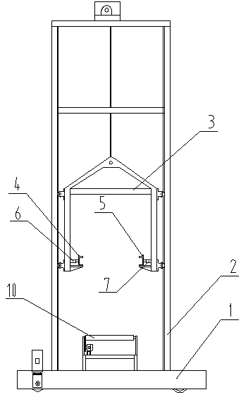
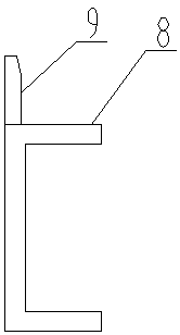
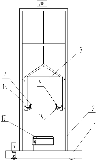
[0016] figure 1 and figure 2 It shows a first embodiment of the roadway stacker used in dense storage warehouses of the present invention, including a traveling trolley 1, a frame 2 vertically installed on the traveling trolley 1, and a lifting platform 3 that lifts along the frame 2, Shuttle car guide rail 4 is installed on the left side of lifting platform 3, and shuttle car guide rail 5 is installed on the right side, and the upper part of shuttle car guide rail is provided with the shelving surface 8 of goods, is provided with stopper 9 on the shelving surface 8, and the stopper 9 uses For the pushing and blocking of goods, the lifting platform 3 is also equipped with a traverse mechanism. The traverse mechanism is a cylinder 6 and a cylinder 7. The cylinder 6 is installed on t...


PUM


Abstract

The invention discloses a roadway stacking machine for a dense repository. The roadway stacking machine comprises a walking vehicle (1), a machine frame (2), a lifting table (3), a shuttle vehicle guide rail (4) and a shuttle vehicle guide rail (5), wherein the machine frame (2) is perpendicularly installed on the walking vehicle (1), the lifting table (3) ascends and descends along the machine frame, and the shuttle vehicle guide rail (4) and the shuttle vehicle guide rail (5) are installed on the left side and the right side of the lifting table respectively. Goods placement faces are arranged on the upper portion of the shuttle vehicle guide rails. The lifting table is further provided with a transverse movement mechanism. The transverse movement mechanism pushes the two shuttle vehicle guide rails to transversely move in the opposite directions. The walking vehicle (1) is further provided with a conveying device (10). By combining opposite-direction transverse movement of the shuttle vehicle guide rails and the lifting movement of the lifting table, the goods can be loaded and unloaded among the shuttle vehicle guide rails, the lifting table and the conveying device (10), and the roadway stacking machine is simple in structure and high in loading and unloading speed.

Description

technical field [0001] The invention relates to a cargo lifting device, in particular to a roadway stacker for dense storage warehouses. Background technique [0002] The dense storage warehouse is composed of multi-layer penetrating storage shelves, shuttle cars and stackers or roadway stackers. The shuttle cars travel on the guide rails under the shelves, and the shuttle cars lift the goods from the shelves from under the goods and transport them to After specifying the location, the goods are placed on the shelf. The stacker or roadway stacker is used for loading and unloading and up and down transportation of goods. The roadway stacker can operate for multi-row, multi-layer through storage shelves. The stacker realizes the loading and unloading of goods through the telescopic forks installed on the lifting platform. During the loading and unloading process of goods, the forks have a telescopic movement. When storing long-sized goods, the telescopic distance of the forks ...

Claims


Application Information

Patent Timeline
Patent Type & Authority Patents(China)
IPC IPC(8): B65G1/04
Inventor 毕玉玲
Owner 徐州天辰货架制造有限公司
Learn More